Automatic monitoring system for thermal energy storage plants

a technology of automatic monitoring and thermal energy storage, which is applied in the direction of lighting and heating equipment, instruments, and domestic cooling equipment, etc., can solve the problems of two monitoring systems being inaccurate, gaining widespread exposure, and affecting the operation of the first system

Inactive Publication Date: 2007-01-16
COLASSO FRANCISCO J +2
View PDF24 Cites 9 Cited by
  • Summary
  • Abstract
  • Description
  • Claims
  • Application Information

AI Technical Summary

Benefits of technology

[0022]The primary object of the present invention is to provide an automatic monitoring system for thermal energy storage plants that is accurate.
[0023]A further object of the present invention is to provide an automatic monitoring system for thermal energy storage plants that is affordable.
[0024]An even further object of the present invention is to provide an automatic monitoring system for thermal energy storage plants that is adaptable.

Problems solved by technology

Recently, however, the concept has gained widespread exposure due the deregulation of energy rates and consequent changes in energy pricing policies.
Some external factors make these two monitoring systems inaccurate.
The first system is inaccurate due to rainwater and high humidity affecting the internal water level, especially during the summer months.
Despite best efforts to tightly seal the tanks, rainwater and humidity enter the tanks, causing the internal water level to rise.
Thus, the sensors are relaying inaccurate information to the central control.
During the dry season, water evaporation from the tanks will also lead to inaccurate ice inventory readings.
Additionally, oftentimes the level sensors in the plastic tubes located outside the tanks go bad due to constant exposure to the elements.
The main causes for the inaccurate ice inventory level readings when using the second system are outdoor ambient temperature changes and temperature sensors failures.
Inaccuracy in ice inventory level readings has a direct consequence: inefficiency.
Inaccuracy in ice inventory level readings risks not having air conditioning in a facility or no cooling available for an industrial process during the on peak hours of the day.
In the occurrence of such an event, the owner has the option of running the chiller(s) during the on peak hours at great expense.
Although accurate and reliable, the third and fourth systems include expensive, complicated to manufacture and difficult to install parts.
Thus, cost, downtime and technical difficulties to adapt to existing TES have kept these systems out of the market.

Method used


Image

  • Automatic monitoring system for thermal energy storage plants
  • Automatic monitoring system for thermal energy storage plants
  • Automatic monitoring system for thermal energy storage plants

Examples


Embodiment Construction

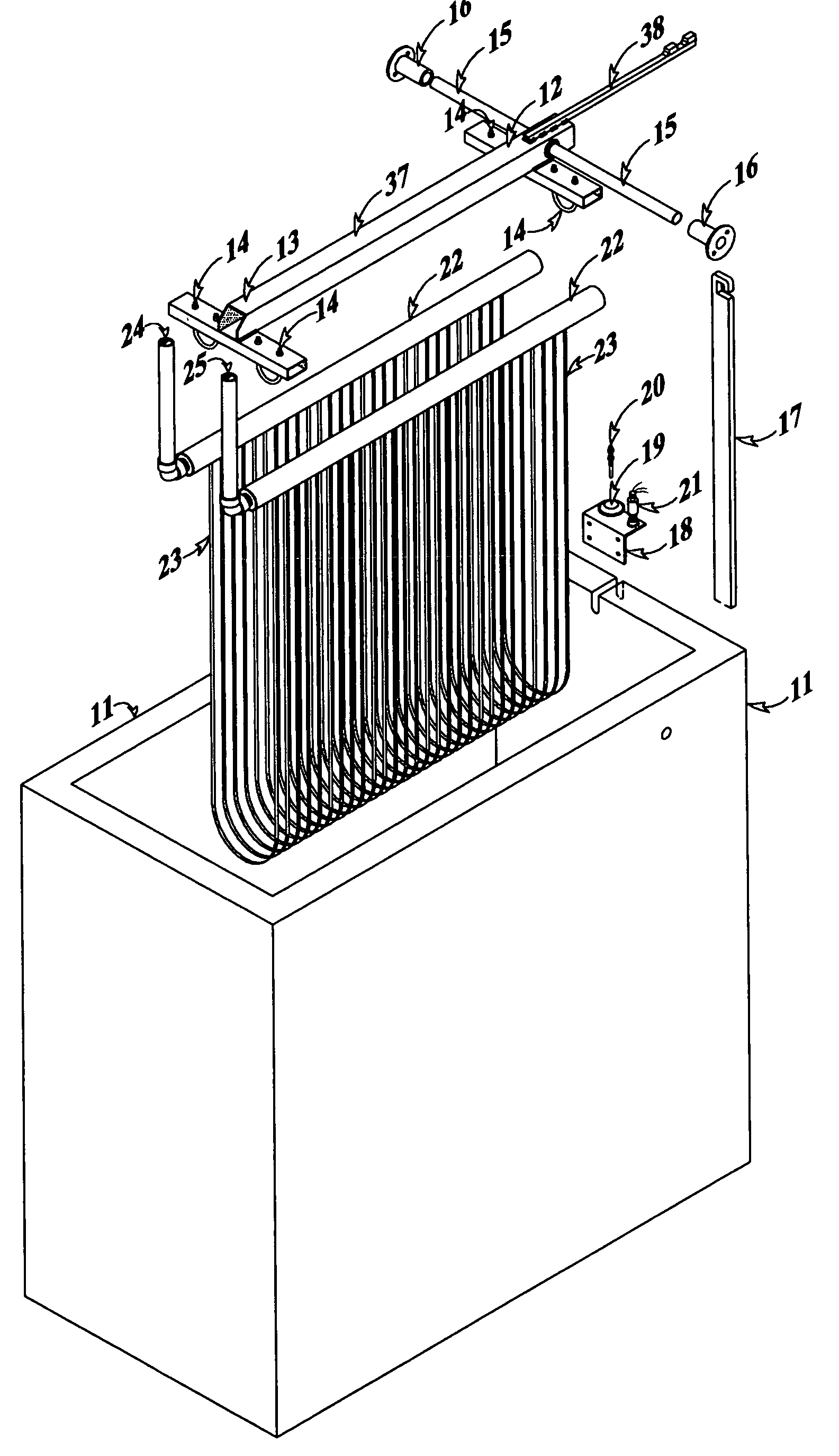
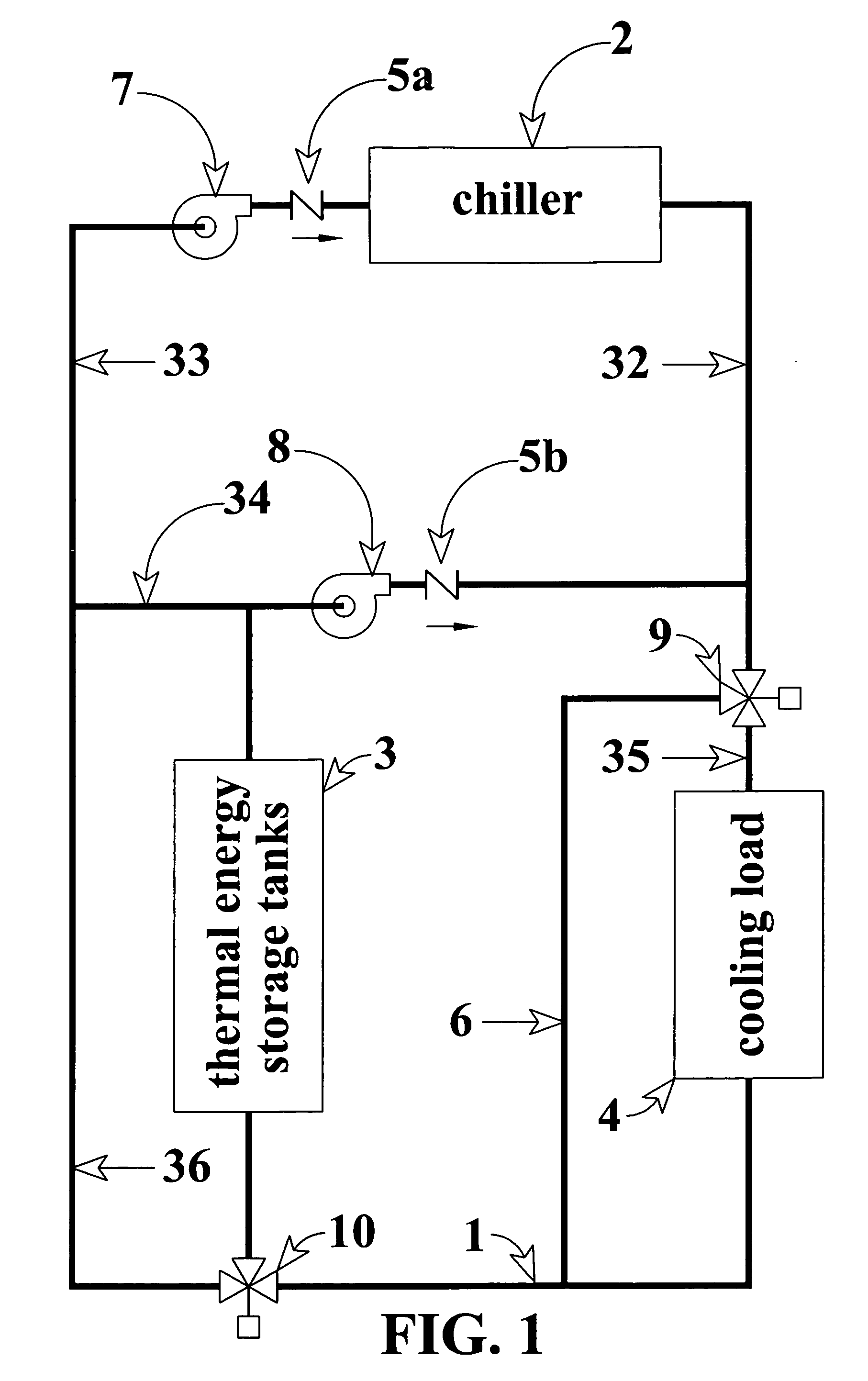
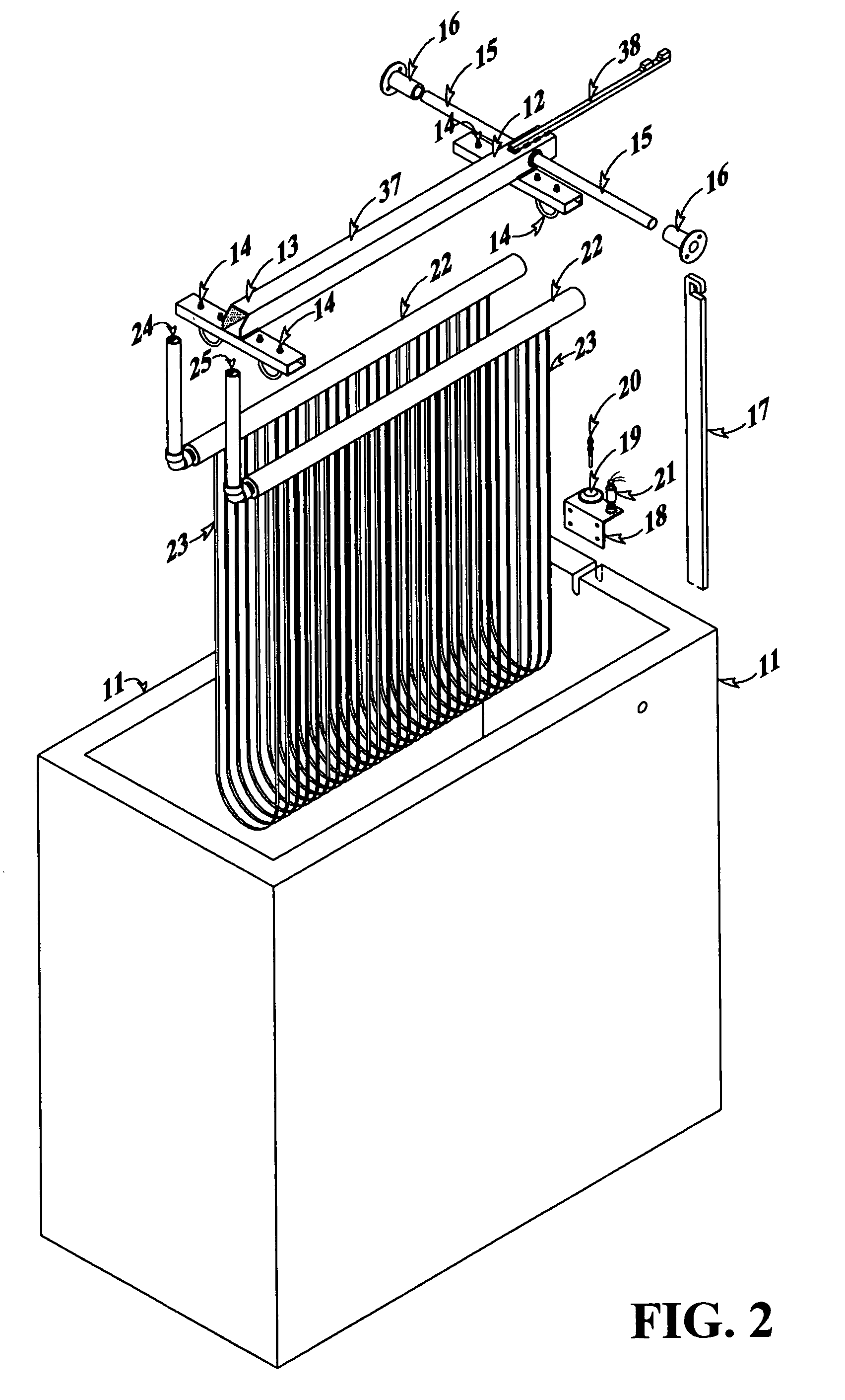
[0040]For purposes of describing the preferred embodiment, the terminology used in reference to the numbered components in the drawings is as follows:[0041]1. piping loop[0042]2. chiller[0043]3. thermal energy storage tanks[0044]4. cooling load[0045]5a. chiller check valve[0046]5b. loop check valve[0047]6. cooling load bypass piping[0048]7. chiller pump[0049]8. thermal energy storage tanks pump[0050]9. cooling load three-way bypass valve[0051]10. thermal energy storage tanks three-way bypass valve[0052]11. pilot ice tank[0053]12. proximal end of pivoting arm[0054]13. distal end of pivoting arm[0055]14. pivoting arm connecting u-bolts[0056]15. pivoting arm crossbar[0057]16. pivoting arm crossbar bearings[0058]17. pivoting arm counterweight[0059]18. hydraulic bellow support[0060]19. hydraulic bellow[0061]20. adjustable calibration rod[0062]21. pressure transducer[0063]22. heat exchanger heads[0064]23. heat exchanger coil[0065]24. heat exchanger inlet[0066]25. heat exchanger outlet[006...


PUM


Abstract

An automatic monitoring system for thermal energy storage (TES) plants wherein a pilot ice tank (11) uses Archimedes' principle to determine the ice inventory level by measuring the resultant force (28) of the algebraic addition of the weight of the ice and the reaction of the water pushing the ice up with a force equal to the weight on the water displaced by the volume of the ice. The resultant force (28) applied on a pivoting arm (37) is transferred to a liquid filled bellow (19) and is transformed into hydraulic pressure. The instantaneous hydraulic pressure is transferred to a pressure transducer (21) which converts the hydraulic pressure into an electric current. The electric current is then sent as an electronic analog input to the central control panel (30) of the TES for analysis or display.

Description

BACKGROUND OF THE INVENTION[0001]This invention relates monitoring systems for thermal energy storage (TES) plants, more specifically, an automatic monitoring system for TES plants wherein the system, when connected to a central control, acts as a pilot ice tank for the new and / or existing TES plants of all sizes and types to automatically and precisely monitor ice inventory to further improve efficiency and energy savings.[0002]Immediate application of the invention relates to the capacity of the pilot ice tank to produce and relay to the central control of the TES information regarding available ice inventory in the TES on a realtime basis. This realtime ice inventory level tells the owner and / or operator of the TES how much cooling capacity is available in the main ice tanks at any given time.[0003]Based on the information provided by the pilot ice tank, an owner or operator of the TES plant can create records to track ice inventory levels in the central control of the TES. These...

Claims


Application Information

Patent Timeline
Patent Type & Authority Patents(United States)
IPC IPC(8): F28D1/06F25D3/00F25D16/00F28D20/02G01F23/00G01F23/20G01G5/02
CPCF25D3/005F28D20/021G01F23/20G01G5/02G01F23/0038F25D16/00Y02E60/145Y02E60/14
Inventor COLASSO, FRANCISCO J.CROSSA, DARWINMADRIGAL, HUGO
Owner COLASSO FRANCISCO J
Why Eureka
Try Eureka