Image reproducing method, image display apparatus and picture signal compensation device

a picture signal compensation and image display technology, applied in the field of image reproducing method, image display apparatus and picture signal compensation device, can solve the problems of incomplete linear processing, inability to obtain an accurate reproduction of an original image (picked up image, inability to properly reproduce an input image, etc., and achieve high display quality and high display quality

Inactive Publication Date: 2007-01-30
SHARP KK
View PDF37 Cites 38 Cited by
  • Summary
  • Abstract
  • Description
  • Claims
  • Application Information

AI Technical Summary

Benefits of technology

[0026]It is an object of the present invention to reproduce an image with a high display quality. In addition, a further object of the present invention is to provide

Problems solved by technology

However, when the average input signal level of brightness G is less than about 60%, or when it is more than about 60%, the gamma value γ(G) of an image output of the CRT display device does not show 2.2, which results in incomplete linear processing, thus failing to obtain an accurate reproduction of an original image (picked up image) on a display.
With this output brightness property is obtained an image which gives the impression that a whole image looks bleached and out of focus when viewed, thus failing to properly reproduce an input image.
Therefore, a viewer feels that a whole screen is so glaring that he or she cannot fully recognize a slight difference in brightness in a bright portion, thereby being given the impression that the screen is apparently in a state of whiteout.
Further, on the contrary, when displaying a dark image having low average brightness, though a dark portion is reproduced substantial

Method used


Image

  • Image reproducing method, image display apparatus and picture signal compensation device
  • Image reproducing method, image display apparatus and picture signal compensation device
  • Image reproducing method, image display apparatus and picture signal compensation device

Examples


first embodiment

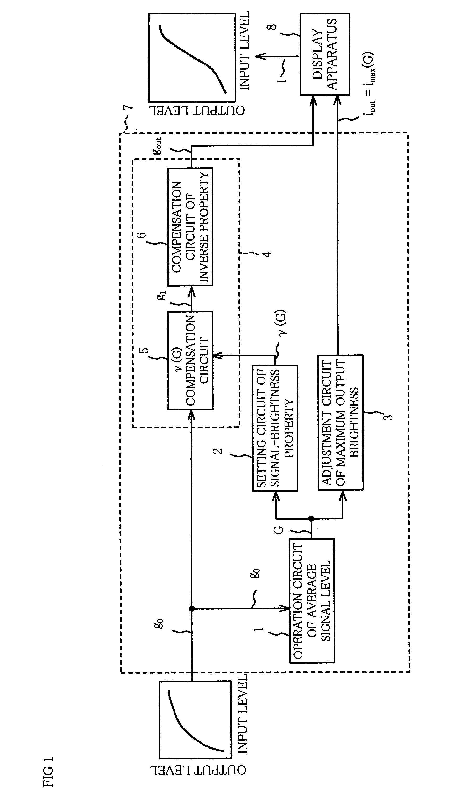
[0077]The following will explain one embodiment of the present invention with reference to FIG. 1.

[0078]As shown in FIG. 1, an image display apparatus of the present embodiment includes a display apparatus (display section) 8 having a plurality of pixels (not shown) for displaying an image; and a picture signal compensation device 7, where a picture signal g0 (signal level of brightness g0) which includes a pixel signal representing information on each pixel is inputted to the display apparatus 8 via the picture signal compensation device 7.

[0079]The picture signal compensation device 7 includes an operation circuit of average signal level (“average signal level operation circuit”, hereinafter; average signal level operation section) 1 for performing an operation on an average level of all the pixel signals as an average input signal level of brightness G, a setting circuit of signal-brightness property (“input signal-output brightness property setting circuit”, hereinafter; input s...

second embodiment

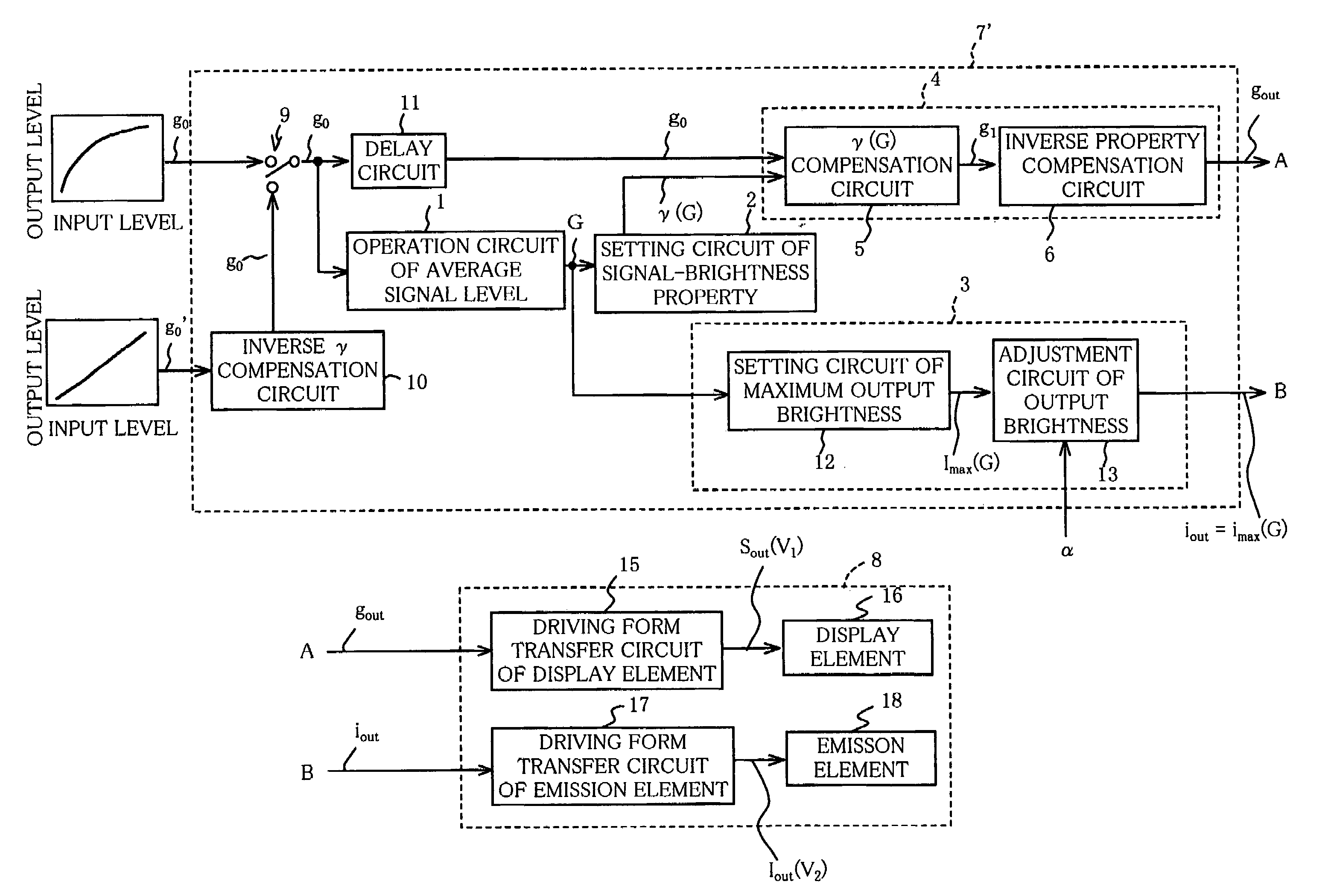
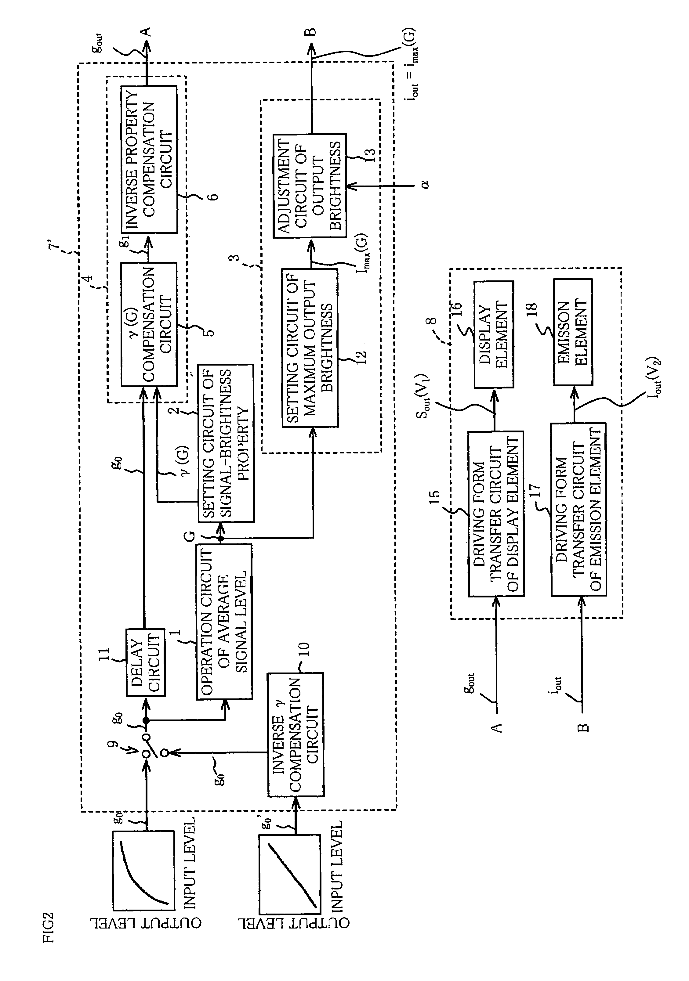
[0106]Next, the following will explain a desired example of the embodiment explained in the First Embodiment with reference to FIGS. 2 and 3. Note that, for ease of explanation, members having the same functions as those shown in the drawings pertaining to the First Embodiment above will be given the same reference numerals, and explanation thereof will be omitted here.

[0107]An image display apparatus of the present embodiment, as shown in FIG. 2, includes a picture signal compensation device 7′ and the display apparatus 8 capable of separately control an emission element and a display element (switching element).

[0108]The display apparatus 8 has a non-emission type display element 16, such as a liquid crystal panel including a plurality of pixels, which is not shown, a driving form transfer circuit of display element (“display element driving form transfer circuit”, hereinafter) 15, such as a liquid crystal driving circuit for converting a picture signal gout outputted from the pic...

third embodiment

[0125]Next, the following will explain another embodiment of the present invention with reference to FIGS. 4 and 5. Note that, for ease of explanation, members having the same functions as those shown in the drawings pertaining to the First and Second Embodiments above will be given the same reference numerals, and explanation thereof will be omitted here.

[0126]As shown in FIG. 4, an image display apparatus according to the present embodiment has a picture signal compensation device 27 and a display apparatus 28 in which a display element (switching element) itself functions as an emission element.

[0127]The display apparatus 28 includes an emission type display element 23, such as a CRT having a plurality of pixels, which is not shown, a driving form transfer circuit of emission type display element (“emission type display element driving form transfer circuit”, hereinafter) 22 for converting a picture signal gout′ outputted from a picture signal compensation device 27 into a signal...


PUM


Abstract

When reproducing an image by a display apparatus having a plurality of pixels, in an average signal level operation circuit is performed an operation to obtain an average signal level which is an average level of all the pixel signals in a picture signal including a pixel signal representing information of a pixel, then, according to this average signal level, in an input signal-output brightness property setting circuit is set an input signal-output brightness property representing variations in brightness of a pixel with respect to a level of the pixel signal, then, the compensation of the picture signal is performed either to satisfy the input signal-output brightness property thus set in a signal compensation section or to allow variations in maximum output brightness of a pixel of the display apparatus according to the average signal level in a maximum output brightness adjustment circuit, so as to output the picture signal subject to compensation to the display apparatus.

Description

FIELD OF THE INVENTION[0001]The present invention relates to an image reproducing method for reproducing an image by a display apparatus, and an image display apparatus having a function to adjust output brightness of a display (display apparatus) when reproducing an image, and a display picture signal compensation device, and in particular to an image reproducing method, an image display apparatus and a picture signal compensation device which are capable of image reproduction with high definition.BACKGROUND OF THE INVENTION[0002]Conventionally, gamma adjustment and brightness adjustment in correspondence with an input picture signal have been available in an image display apparatus. The gamma adjustment adjusts an input signal-output brightness property (a variation in an output brightness to a variation in an input signal; it is called a gamma property) of an image display apparatus. By such adjustments to control brightness, a nuance of color (chromaticity) and a contrast ratio ...

Claims


Application Information

Patent Timeline
IPC IPC(8): G09G3/30G09G3/34G09G5/10
CPCG09G3/3406G09G5/10G09G2320/0606G09G2360/16G09G2320/0633G09G2320/0673G09G2320/0626
Inventor OKAMOTO, SHIGETSUGUSUGINO, MICHIYUKI
Owner SHARP KK
Why Eureka
Try Eureka