Method and apparatus for dynamically configuring redundant area of non-volatile memory

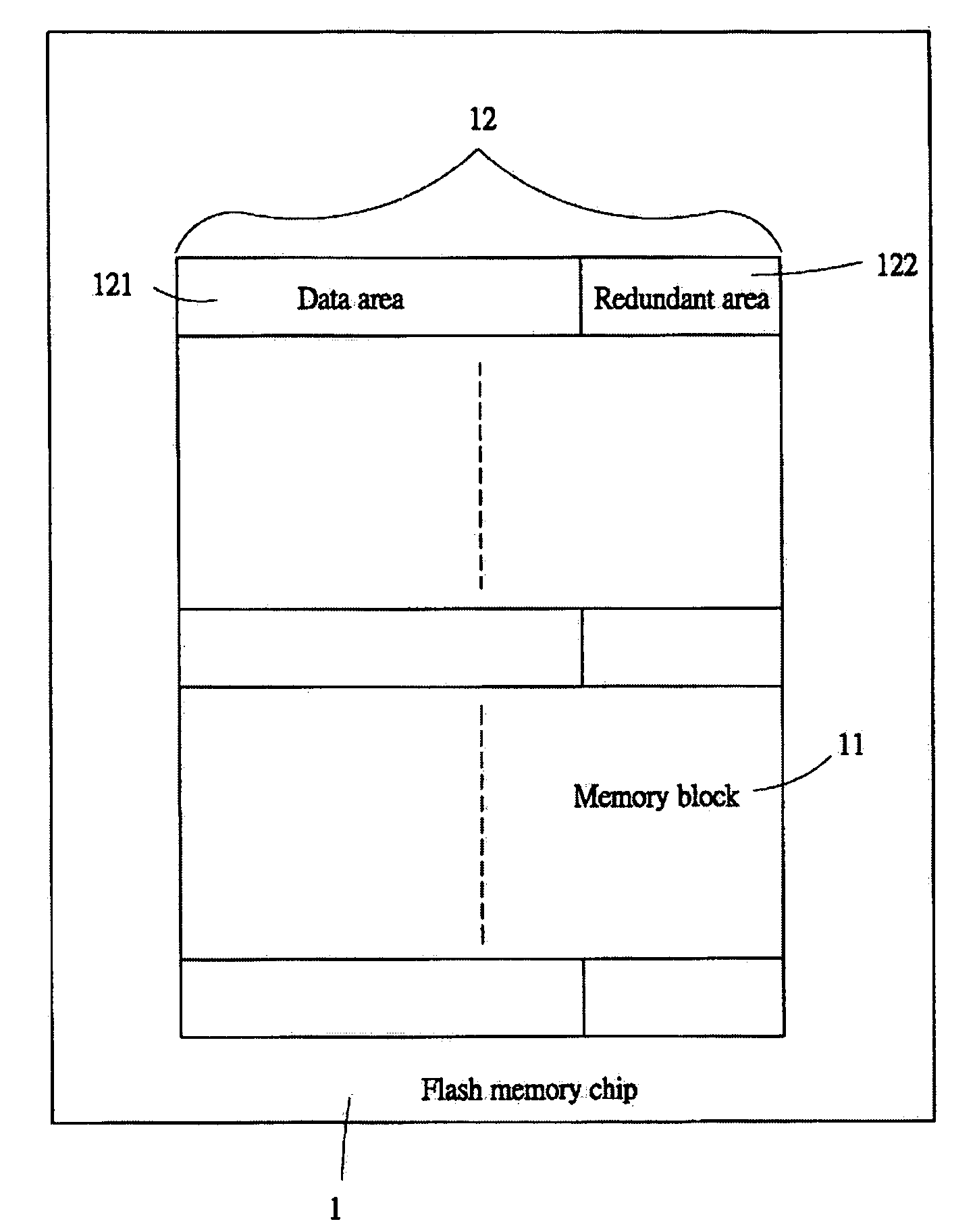
a non-volatile memory and redundant area technology, applied in the direction of memory adressing/allocation/relocation, digital storage, instruments, etc., can solve the problems of high cost, time-consuming and laborious, and the redundant area b>122/b> in the flash memory b>1/b> cannot be accessed by the conventional flash memory controller, so as to shorten the development cycle and reduce the development cost

Active Publication Date: 2007-03-06
GENESYS LOGIC INC
View PDF3 Cites 11 Cited by
  • Summary
  • Abstract
  • Description
  • Claims
  • Application Information

AI Technical Summary

Benefits of technology

Enables access to larger memory pages using existing buffer sizes, reducing development time and cost by allowing conventional hardware to support new flash memory structures without hardware redesign.

Problems solved by technology

However, the structure of data area 121 and redundant area 122 in the flash memory 1 cannot be accessed by the conventional flash memory controller because the buffer size of the conventional flash memory controller is too small.
This does not only take time and high cost but also delay the product's mass production schedule

Method used


Image

  • Method and apparatus for dynamically configuring redundant area of non-volatile memory
  • Method and apparatus for dynamically configuring redundant area of non-volatile memory
  • Method and apparatus for dynamically configuring redundant area of non-volatile memory

Examples


Embodiment Construction

[0020]FIG. 2 shows an exemplary memory page configuration for a memory 100 according to one embodiment of the invention. Take Samsung 128M-byte flash memory as example. At first, the status information of the flash memory is read. The memory 100 comprises 1024 blocks 10, with each block 10 having 64 pages 20, as shown in FIG. 2. Each page 20 is configured to comprise a plurality of consecutive data areas 21 and at least one redundant area 22. In the embodiment shown in FIGS. 2 and 3, there are 4 redundant areas 22. Each page 20 is exemplified as 2112 (=2K+64) bytes. Each data area 21 has 512 bytes, and each redundant area 22 has 16 bytes. Similarly, if each page is configured into 8 data areas 21 and 8 redundant areas 22, the sizes of the data area 21 and the redundant area 22 are 256 bytes and 8 bytes, respectively. The redundant areas 22 preferrably interleave the data areas 21, that is, a redundant area 22 is placed between two consecutive data areas 21. Finally, the status infor...


PUM


Abstract

A method and an apparatus for dynamically configuring the redundant areas of a non-volatile memory is provided wherein each page of a memory is configured into a plurality of data areas and a plurality of redundant areas. The redundant areas interleave the data areas, or are arranged behind any data area. The system information and the status information is programmed into each data area of the page according to the original status information, so as to allow the flash drive to load a data area and an associated redundant area for each access operation with a smaller buffer.

Description

BACKGROUND OF THE INVENTION[0001]1. Field of the Invention[0002]The present invention relates to a method and an apparatus for dynamically configuring the redundant area in a non-volatile memory and, more particularly, to a method and an apparatus for configuring data areas and redundant areas in a flash memory and reducing the buffer size of the storage device for accessing data.[0003]2. The Related Arts[0004]Flash memory is widely used in versatile digital equipment, such as digital cameras, TV game boxes, and flash drives. As the fabrication technology improves, the capacity of flash memory also increases greatly. For example, FIG. 1 shows the 1G-bit flash memory chip 1 manufactured by Samsung. The flash memory has the capacity of 128M bytes, divided into 1024 blocks 11, with each block having 64 pages 12. In each page 12, there are 2K+64 bytes, where 2K bytes are the data area 121, and the 64 bytes are the redundant area 122, located at the end of the data area 121 for storing s...

Claims


Application Information

Patent Timeline
Patent Type & AuthorityPatents(United States)
IPC IPC(8): G11C8/00G06F12/02G11C29/00
CPCG11C29/82
InventorYANG, CHENG-CHIH
OwnerGENESYS LOGIC INC