HDMI connector assembly

Inactive Publication Date: 2007-05-01
YING WAN FA
View PDF5 Cites 27 Cited by
  • Summary
  • Abstract
  • Description
  • Claims
  • Application Information

AI Technical Summary

Benefits of technology

[0007]It is therefore an object of the present invention to provide a HDMI electrical connector assembl

Problems solved by technology

Further, it is difficult of soldering.
Furthermore, solder may connect two adjacent thin electrical terminals together and result some of the terminals in short-circuit.
Also, it is difficult to control the soldering quality.
It is often that such soldering process will easily raise defects in some of soldering points on both PCB and connector assembly, resulting in a signal transmission performance degradation.
Fur

Method used


Image

  • HDMI connector assembly
  • HDMI connector assembly
  • HDMI connector assembly

Examples


Example

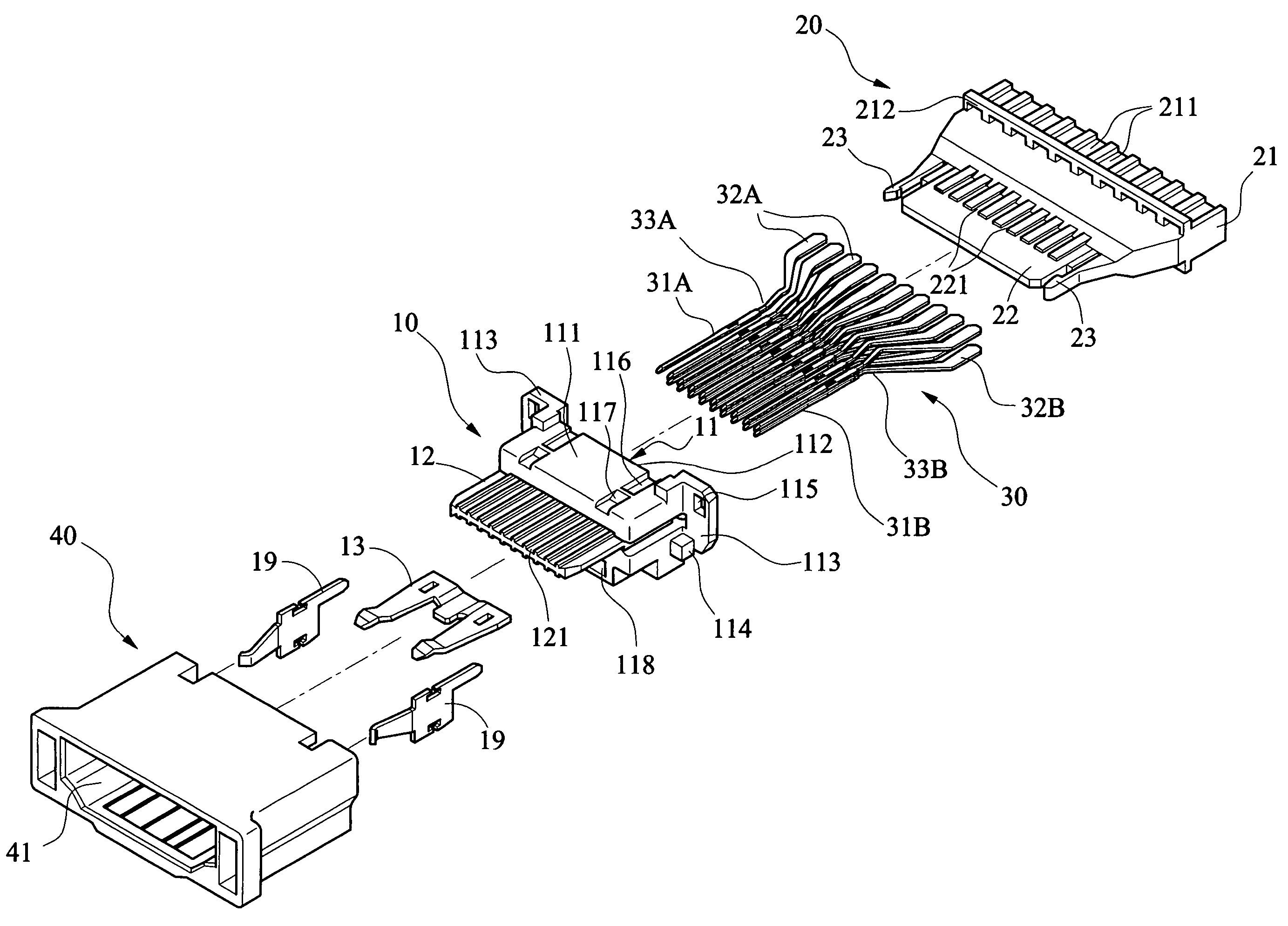
[0022]Referring to FIGS. 4 to 7, a female HDMI connector assembly in accordance with a first preferred embodiment of the invention comprises an insulative body 10, an insulative seat 20, two rows of a plurality of conductors 30, and a housing 40. Each component is discussed in detailed below. The insulative body 10 comprises a body member 11 and a plate 12. The body member 11 includes a central channel 111 through the body member 11, a plurality of parallel grooves 112 on top and bottom of the channel 111, two side wings 113, two positioning blocks 114 each adjacent the wing 113, two holes 115 each on the wing 113, two troughs 116 each adjacent side of a top, two ridges 117 each in the trough 116, and a lower slot 118 under the plate 12. The insulative body 10 further comprises a resilient member 13 fitted in the slot 118. The plate 12 comprises two rows of a plurality of parallel terminal cavities 121 aligned with the grooves 112.

[0023]The insulative seat 20 comprises a rear member...


PUM


Abstract

A HDMI connector assembly includes an insulative body including a body member including a central channel therethrough and parallel grooves on top and bottom of the channel, and a plate including two rows of parallel terminal cavities aligned with the grooves; an insulative seat provided in the channel and including a rear member including parallel furrows on its top and bottom, and a front member including parallel depressions; two rows of conductors provided in the depressions, the furrows, the grooves, and the terminal cavities, each conductor including a front electrical terminal and a rear solder member wherein the solder members of one row and the solder members of the other row are bent in opposite directions; and a housing for receiving the insulative body. The invention has advantages of increased quality and signal transmission performance, and causing no pollution.

Description

BACKGROUND OF THE INVENTION[0001]1. Field of Invention[0002]The present invention relates to electrical connectors and more particularly to a HDMI (high definition multimedia interface) connector assembly with improved characteristics.[0003]2. Description of Related Art[0004]A conventional HDMI electrical connector is for transmitting data, audio, and video signals along a cable and has a high performance transmission interface independent of cable length. The well known connector is fixedly connected to PCB (printed circuit board) (not shown) by soldering. Also, conductor spacing is very small (e.g., about 1 mm) and solder area is thus small. Further, it is difficult of soldering. Furthermore, solder may connect two adjacent thin electrical terminals together and result some of the terminals in short-circuit. Also, it is difficult to control the soldering quality.[0005]As shown in FIGS. 1 to 3, a PCB 92 is inserted between two rows of conductors 91 in the conventional HDMI connecto...

Claims


Application Information

Patent Timeline
IPC IPC(8): H01R12/00
CPCH01R13/502
Inventor YING, WAN-FA
Owner YING WAN FA
Why Eureka
Try Eureka