Network system, transmission method, and computer program

a network system and transmission method technology, applied in the field of network system, transmission method, computer program, to achieve the effect of fair allocation of bands

Inactive Publication Date: 2007-05-15
FURUKAWA ELECTRIC CO LTD
View PDF3 Cites 8 Cited by
  • Summary
  • Abstract
  • Description
  • Claims
  • Application Information

AI Technical Summary

Benefits of technology

[0006]It is an object of the present invention to provide a network system, a transmission method and a computer program which can ensure fairness in the allocation of bands to VLAN groups while securing the convenience of a VLAN, and which can prevent a heavy traffic user from occupying a physical port.

Problems solved by technology

Therefore, if the user transfers data which has a wide transmission band, the data occupies all the bands of a physical link which constitutes the VLAN and the other users cannot hold communication.

Method used


Image

  • Network system, transmission method, and computer program
  • Network system, transmission method, and computer program
  • Network system, transmission method, and computer program

Examples


Embodiment Construction

[0017]A network system, a transmission method and a computer program according to the present invention will be explained herein after with reference to the accompanying drawings.

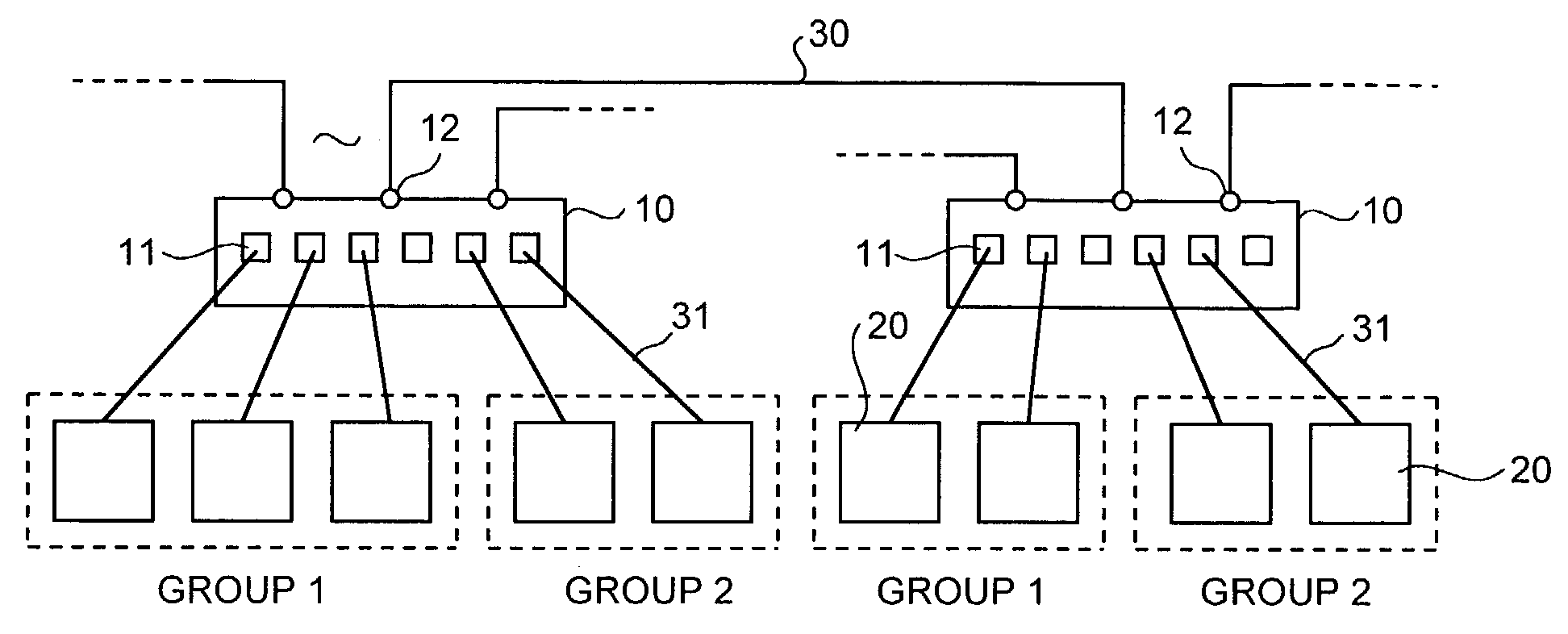
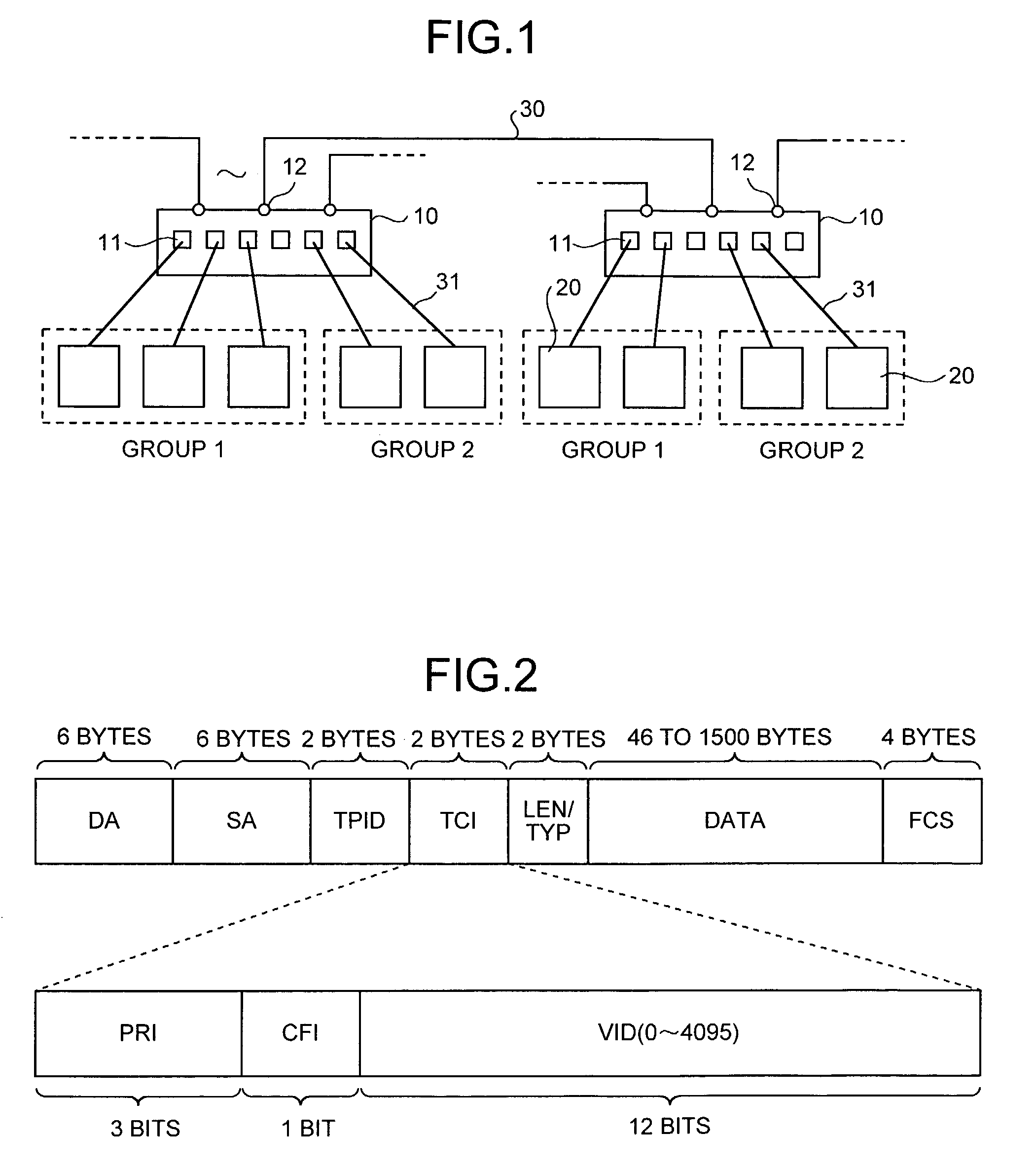
[0018]As shown in the schematic block diagram of FIG. 1, this network system is constituted so that a plurality of terminals 20 are connected, through branch transmission lines 31, to each of a plurality of routers 10 which are mutually connected through a trunk transmission line 30. A plurality of virtual LANs (VLANs) which are constructed on such a network system are realized by multiplexing virtual LANs on the same physical line (port) which constitutes the trunk transmission line 30 and each router 10 has a function of grouping the terminals 20 for each VLAN.

[0019]Information which each terminal 20 communicates through the router 10 consists of packets each of which has a frame structure as shown in FIG. 2 specified, for example, according to IEEE802.1Q. The packet consists of a destination address DA o...


PUM


Abstract

Queues which correspond to each of the LANs in multiplexed virtual LANs are created. Received packets are distributed to the queues in accordance with a VLAN-ID and a destination address included in each of the received packets. The packets are output from the respective queues in a predetermined order, thereby ensuring fairness among the virtual LANs. As a result, even if a user of a virtual LAN transmits data with traffic having a wide transmission band, the virtual LAN does not occupy the band of the physical port and does not hamper transmission of other users.

Description

BACKGROUND OF THE INVENTION[0001]1) Field of the Invention[0002]The present invention relates to a network system which constitutes a virtual local area network (LAN), a transmission method and a computer program.[0003]2) Description of the Related Art[0004]As network systems, there is known a virtual LAN (VLAN) technique which virtually constitutes a LAN as if a plurality of different LANs exist at the same physical port. This technique is specified by IEEE802.1Q or the like and applied. According to this VLAN, tag identifiers (TPID) are provided in packets to be transmitted, respectively, thereby grouping terminal equipment or the like which are connected to LANs. For example, if a VLAN is constituted among a plurality of routers to each of which a plurality of terminals are connected, the terminals are grouped by identifying TPIDs in the packets which pass through the routers. Needless to say, if a VLAN is constituted among a plurality of switching hubs to each of which the termi...

Claims


Application Information

Patent Timeline
Patent Type & Authority Patents(United States)
IPC IPC(8): H04L12/28H04L12/56H04L12/18H04L12/46H04L29/06H04L29/12
CPCH04L12/4641H04L29/12009H04L61/00H04L69/22
Inventor MATSUFURU, NORIO
Owner FURUKAWA ELECTRIC CO LTD
Why Eureka
Try Eureka