Device for fastening a turbocharger

a technology for turbochargers and fastening devices, which is applied in the direction of liquid fuel engines, machine supports, lighting and heating apparatus, etc., can solve problems such as stress in the fastening devi

Inactive Publication Date: 2007-06-12
ABB (SCHWEIZ) AG
View PDF48 Cites 17 Cited by
  • Summary
  • Abstract
  • Description
  • Claims
  • Application Information

AI Technical Summary

Benefits of technology

[0004]The object is, therefore, to provide a fastening device for turbochargers, which has a fastening foot integrally formed in one piece in a gas outlet casing and which can absorb or compensate different thermal expansions of base and gas outlet casing.

Problems solved by technology

Since the turbochargers used at the present time mostly have uncooled casings, with turbochargers being fastened to a mostly relatively cool base, there is the problem of different thermal expansions between turbocharger and base which lead to stresses in the fastening device.

Method used


Image

  • Device for fastening a turbocharger
  • Device for fastening a turbocharger
  • Device for fastening a turbocharger

Examples


Embodiment Construction

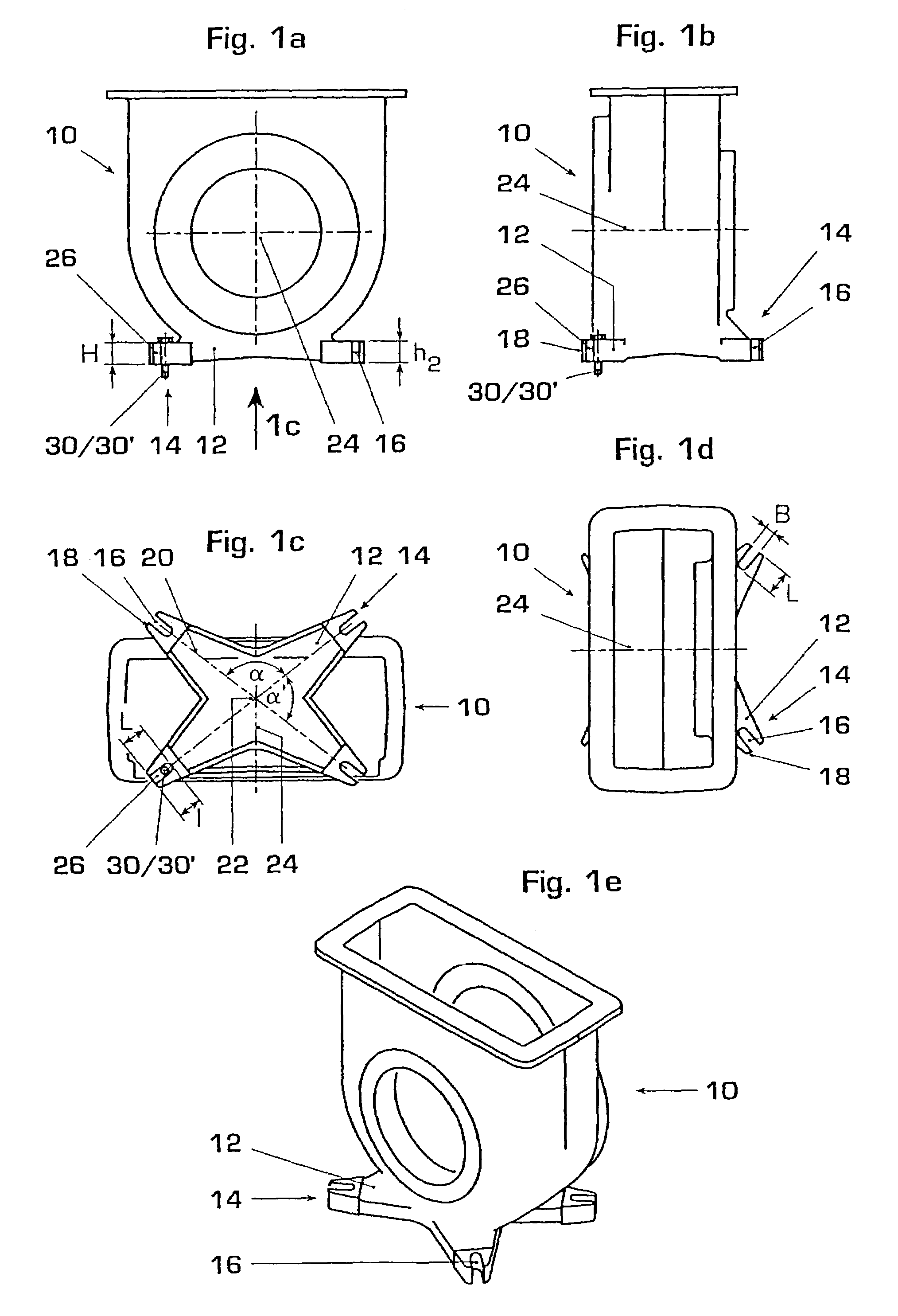
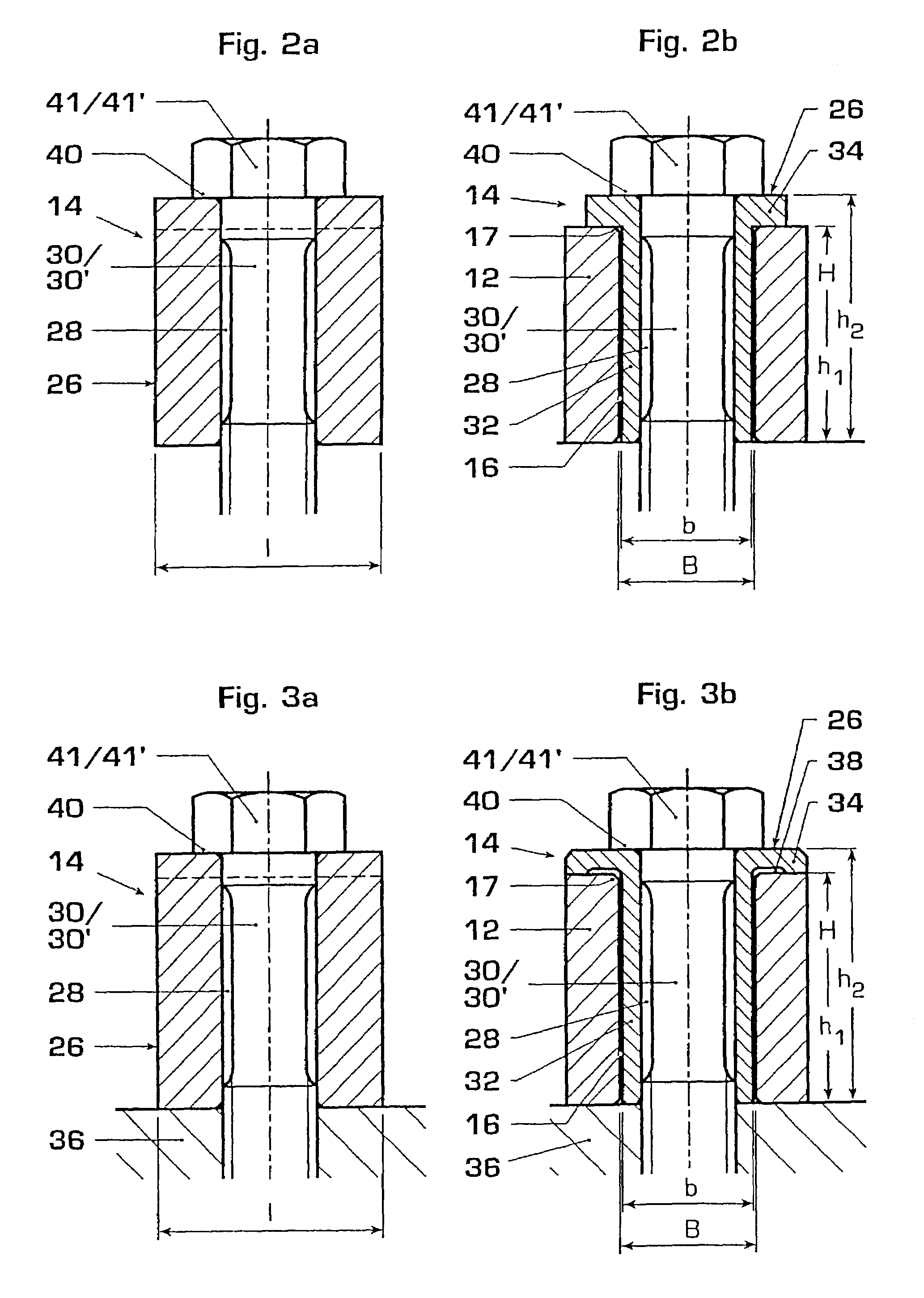
[0020]FIGS. 1a to 1e show a gas outlet casing 10 of a turbocharger, with a fastening foot 12, integrally formed in one piece, corresponding to the fastening device 14 according to the invention. In the example shown, the fastening foot 12 has four long holes 16 which are open towards the periphery 18 of the fastening foot 12. The long holes 16 are oriented with their longitudinal axes 20 in a star-shaped manner in relation to one another. The longitudinal axes 20 have a common center 22 which is located below an axis 24 of the turbocharger (cf. FIG. 1c). The size of the fastening foot 12, the number n of long holes 16 and the angle α,α′ between the longitudinal axes 20 are coordinated with the clamping force and also the weight and special configuration of the turbocharger. Thus, here, the angle α or α′ between the four long holes differs from the generally highly advantageous angle of 90°. The periphery 18 of the fastening foot and therefore, in this example, also the position of t...


PUM


Abstract

A device for fastening a turbocharger to a base, with a fastening foot (12) which is integrally formed in one piece on a gas outlet casing (10) of the turbocharger and which has long holes (16) spaced from one another and preferably arranged in a star-shaped manner in relation to one another. In order to fasten the turbocharger, sliding shoes (26) are capable of being inserted into the long holes (16) and have continuous orifices, through which can be led fastening elements (30, 30′) capable of being fixed in the base.

Description

FIELD OF THE INVENTION[0001]The invention relates to a device for fastening turbochargers to a base according to features described herein.BACKGROUND OF THE INVENTION[0002]There is a series of widely differing possibilities for fastening turbochargers to a base. Since the turbochargers used at the present time mostly have uncooled casings, with turbochargers being fastened to a mostly relatively cool base, there is the problem of different thermal expansions between turbocharger and base which lead to stresses in the fastening device. In order to solve this problem, as a rule, separate fastening feet are introduced between turbocharger and base which, by virtue of a special configuration, can absorb the different expansions. Moreover, these fastening feet also often allow a spatially variable orientation of at least parts of the casing of the turbocharger. Separate fastening feet of the type mentioned are known, for example, from DE-A-4432073 and DE-A13641478.[0003]Turbochargers for...

Claims


Application Information

Patent Timeline
Patent Type & Authority Patents(United States)
IPC IPC(8): F16M3/00F03D11/00F02B39/00F01D25/24F01D25/28F02C6/12F16B5/02F16M7/00
CPCF01D25/243F01D25/28F02C6/12F16M7/00F16B5/02F05D2220/40F05D2230/642
Inventor BATTIG, JOSEFWERRO, JEAN-YVES
Owner ABB (SCHWEIZ) AG
Why Eureka
Try Eureka