Reflection filter

a filter and filter technology, applied in the field of filtering, can solve problems such as distortion of original transmitted signals

Active Publication Date: 2007-06-19
TELEDYNE LECROY
View PDF3 Cites 5 Cited by
  • Summary
  • Abstract
  • Description
  • Claims
  • Application Information

AI Technical Summary

Benefits of technology

[0003]In accordance with the present invention, the reflections created in a signal when there is a change in the impedance of the signal path are used advantageously. When a high or low impedance is encountered in the signal path, a portion of the signal is reflected back in proportion to the impedance change. By obtaining the time at which reflection occurs on the signal, the impedance mismatch location can be pinpointed in the circuit. Once the location is known, in accordance with the invention, a predetermined algorithm is employed to generate a filter that is designed to offset any effects generated by the reflected signal. Filtering such a received signal with a Reflection Filter constructed in accordance with the invention removes the reflected waveform in the sampled signal without significantly effecting the rise time or overshoot of the signal.
[0004]Thus, a user is able to receive an output signal without any noise generated by the reflected signal, even when signal path geometry makes it impossible to precisely impedance match all components along the path.

Problems solved by technology

This is because at any point along the transmission line, that value of the signal will appear as a combination of the originally transmitted signal, and the reflected signal, thus resulting in distortion of the originally transmitted signal.

Method used


Image

  • Reflection filter
  • Reflection filter
  • Reflection filter

Examples


Embodiment Construction

[0018]The present invention is preferably implemented in an oscilloscope, thus allowing for the filtering of signals that are to be tested and viewed on the oscilloscope. However, the invention is not so limited, and may be implemented, in part or in whole, on any electronic instrument that would find benefit from removing the effects of a reflected signal from a signal transmission path.

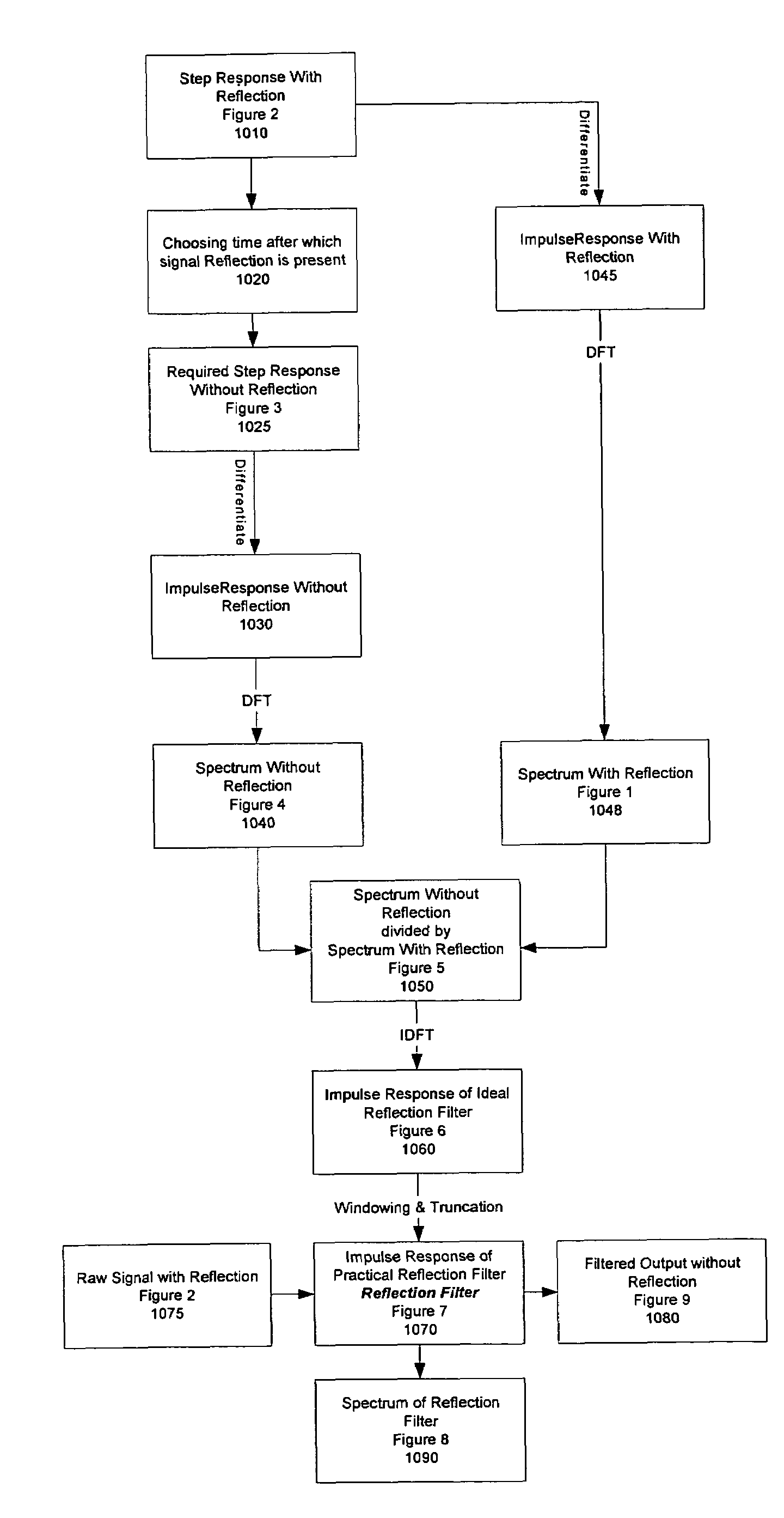
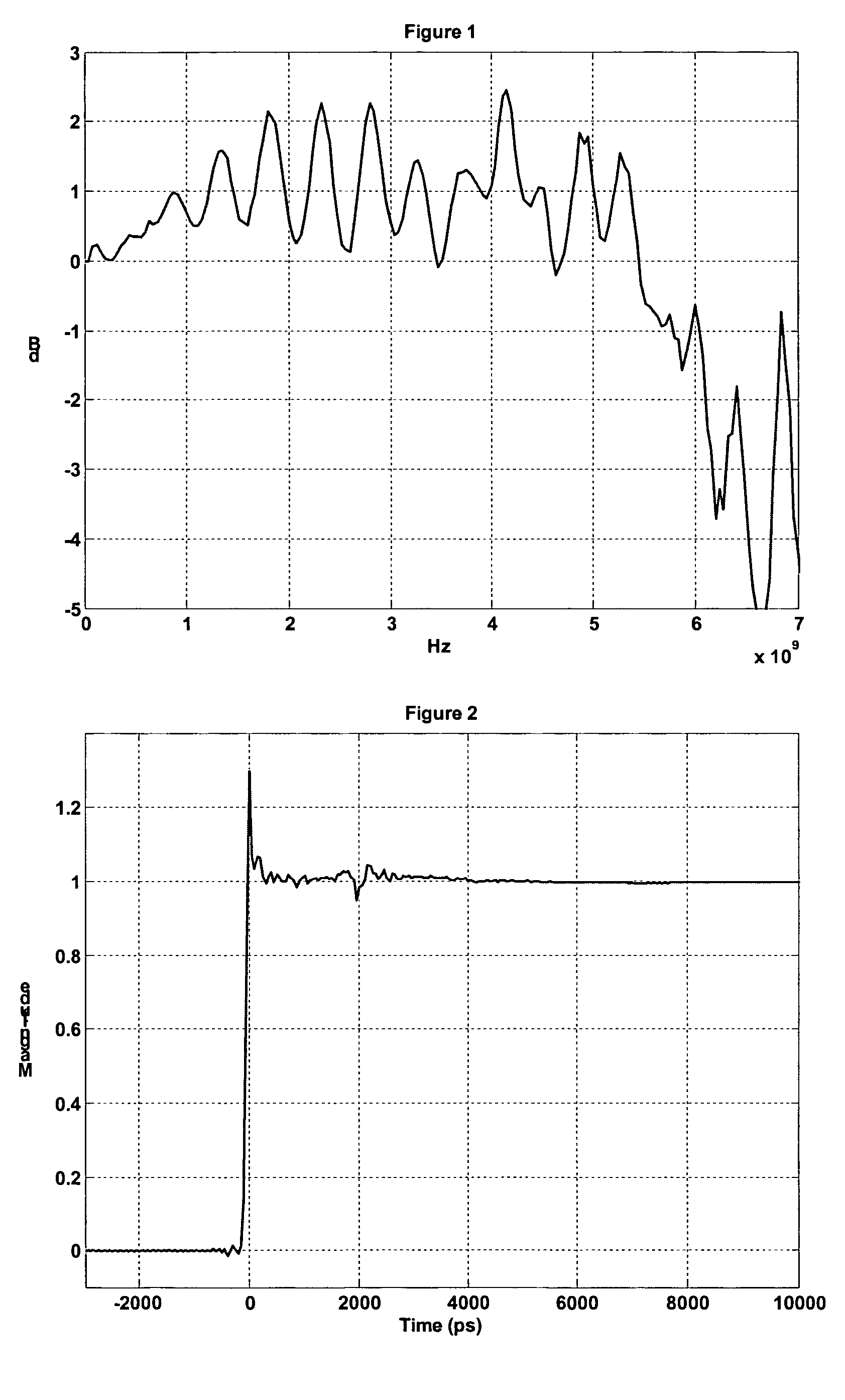
[0019]Referring next to the figures, a first embodiment of the invention will now be described. FIG. 10 is a flowchart showing the overall processing of the reflection filter building process in accordance with the invention. As is shown in FIG. 10, at step 1010, a step response including a reflected signal is obtained. Such a signal is shown in FIG. 2, which depicts an Averaged Step response from the system having a reflection. A multiple number of step responses are acquired with the same system settings and trigger position. These responses at each point for the different step responses are added...


PUM


Abstract

A method and apparatus for generating a reflection filter. The method comprises the steps of determining an averaged step response of an acquired signal and generating a spectrum response from the averaged step response. A time at which a reflection in the averaged step response begins is determined and information in the averaged step response after the determined time when the reflection begins is replaced with an ideal flat line response to generate a required step response. A spectrum response is generated from the required step response and each frequency point of the spectrum response corresponding to the required step response is divided by each frequency point of the spectrum response corresponding to the averaged step response to generate a spectrum of the reflection filter. The result of the dividing step is processed to generate a reflection filter impulse response.

Description

BACKGROUND OF THE INVENTION[0001]Electronic signals are acted upon by transmission through various systems, conduits or the like. These conduits have various inherent physical properties, one of them being impedance. This impedance is the total opposition to the flow of current offered by a circuit. A transmission line that is terminated with a load impedance equal to the characteristic impedance Zo of the line will not reflect an incident wave at that point, and the transmission line is said to be impedance matched. However, a transmission line that is terminated with a load impedance different than Zo will reflect part of an incident wave back toward the source or generator of the signal.[0002]Reflections are often undesirable and should be eliminated. This is because at any point along the transmission line, that value of the signal will appear as a combination of the originally transmitted signal, and the reflected signal, thus resulting in distortion of the originally transmitt...

Claims


Application Information

Patent Timeline
Patent Type & Authority Patents(United States)
IPC IPC(8): G06F17/10
CPCH03H17/0248H03H2017/0072
Inventor SUREKA, ANIRUDH KAILASH
Owner TELEDYNE LECROY
Why Eureka
Try Eureka