Ice lighting device

a technology of lighting device and ice, which is applied in the field of lighting device, can solve the problems of not being widely used, device not known to be widely used, and image difficulty, and achieve the effect of being effectively disposabl

Inactive Publication Date: 2007-07-03
FLEX LIGHTING II
View PDF17 Cites 36 Cited by
  • Summary
  • Abstract
  • Description
  • Claims
  • Application Information

AI Technical Summary

Benefits of technology

[0012]The film 112 is preferably provided as a sheet of inexpensive (and effectively disposable) flexible plastic film, with polycarbonate and acrylic (e.g., polymethyl methacrylate) films having thicknesses of less than 0.75 mm being particularly preferred. Since such films effectively serve as insulators, it is particularly preferred that the film 112 have a thickness of less than 0.5 mm to reduce the possibility that the film 112 might thermally interfere with ice formation and maintenance. The film 112 is preferably coupled to the light source 1

Problems solved by technology

For example, images are sometimes projected onto floors or ceilings, but the images are usually difficult to see unless at least some of the lights are dimmed or turned off.
However, this device is not known to be in widespread use, probably owing to its cost, thermal issues (i.e., heat from the LEDs melting the ice), size, difficulty in installation and removal, and its visibility within the ice when it is not illuminated.
However, this arrangement is also not known to be widely used, probably owing to high cost, the large fiber diameter needed to generate noticeable illumination (which in turn causes difficulties with cable stiffness and bending), the difficulty in forming cables into desired shapes (and retaining them

Method used


Image

  • Ice lighting device
  • Ice lighting device

Examples


Embodiment Construction

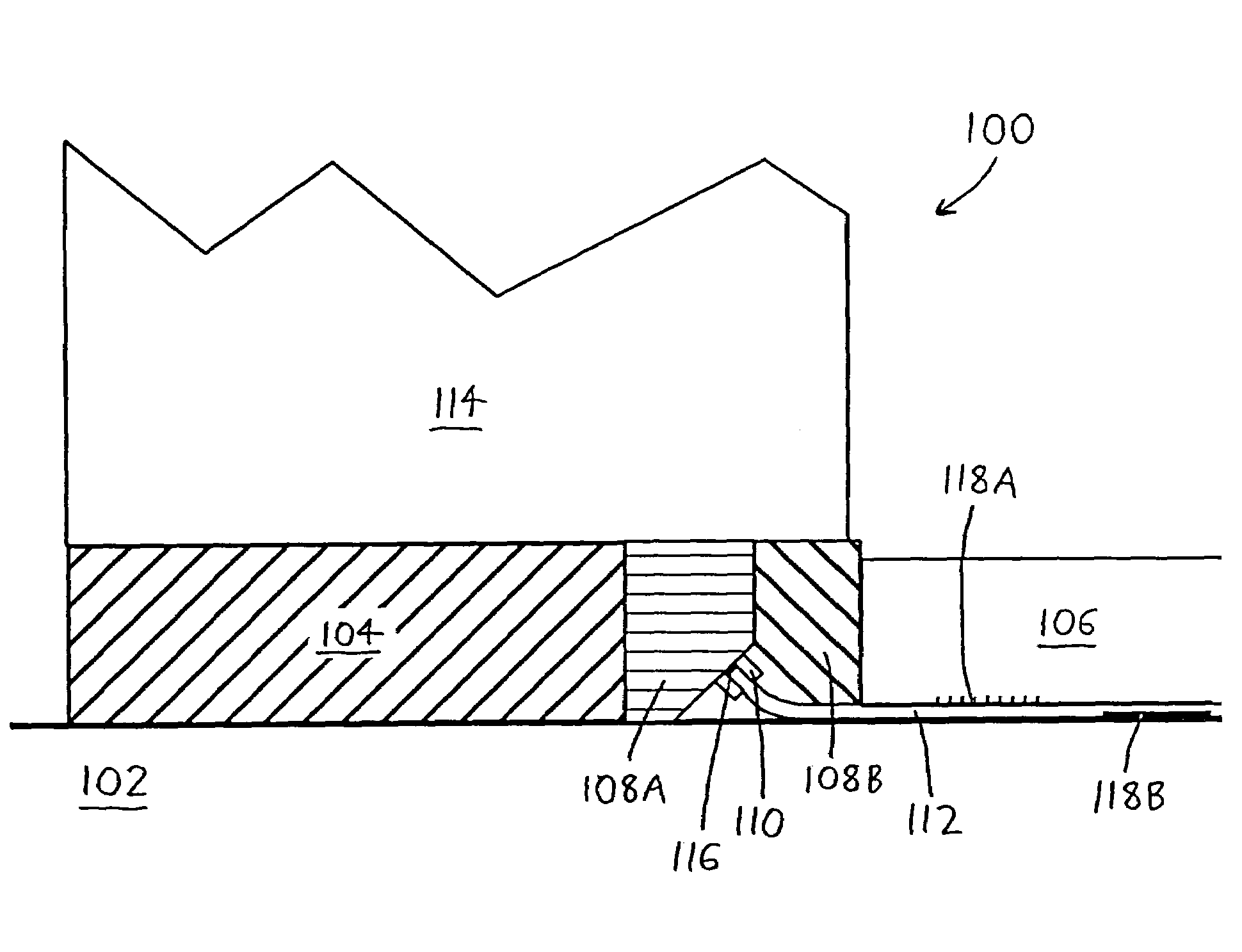
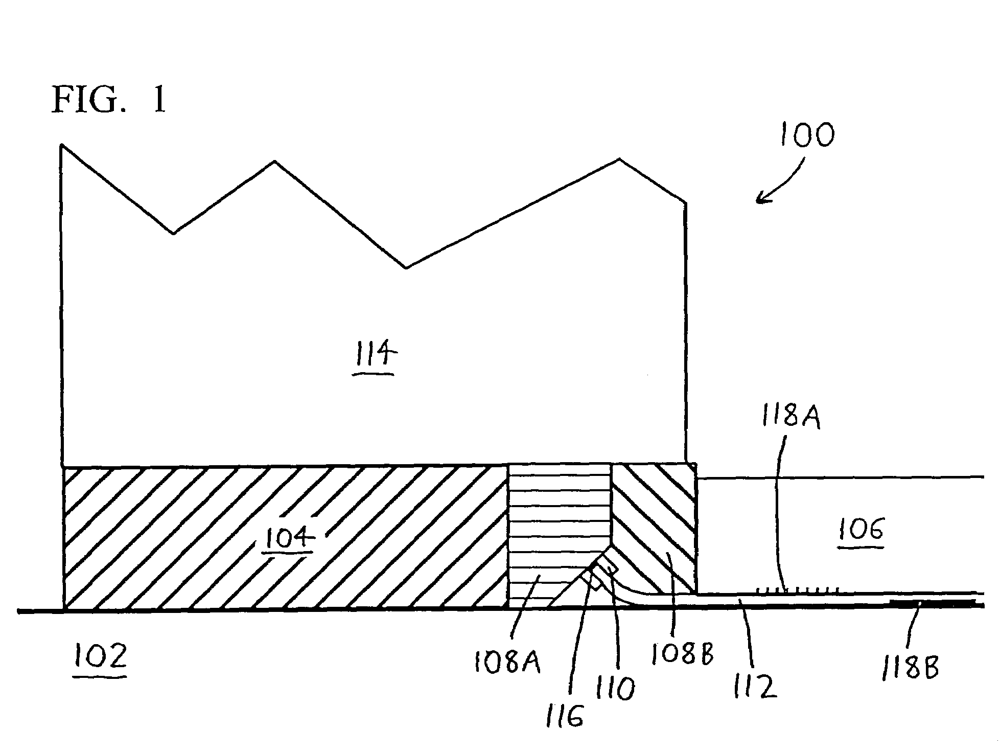
[0016]Looking to FIG. 1, a first exemplary version of the invention is depicted generally by the reference numeral 100. The lighting device 100 is depicted within a typical rink defined by a chilled concrete slab 102, and a dam 104 which rises above the slab 102 to encircle the periphery of a sheet of ice 106. A film mount is then provided in two parts, an inner part 108A and an outer part 108B, between the ice 106 and the inner surface of the dam 104. The inner film mount 108A has a clamp 110 situated thereon to grasp and retain a sheet of light-transmitting film 112, which extends beneath the outer film mount 108B to travel below the ice 106 (which is formed atop the film 112). A dasher board 114 is also provided atop the dam 104 and the film mount 108A / 108B.

[0017]A light source 116 is situated between the opposing parts of the clamp 110 to emit light into the edge of the film 112. The light travels within the interior of the film 112, and so long as the light travels substantiall...


PUM


Abstract

A lighting device for illuminating ice has a sheet of light-transmitting film located below an ice layer and coupled to a light source. The index of refraction of the light-transmitting film is greater than that of the adjoining ice or air so that the light within the film experiences substantial internal reflection. Light is emitted from the film (and the ice surface) at emission regions that disrupt internal reflection.

Description

CROSS-REFERENCE TO RELATED APPLICATION[0001]This application claims priority under 35 USC § 119(e) to U.S. Provisional Patent Application 60 / 555,119 filed 22 Mar. 2004, the entirety of which is incorporated by reference herein.FIELD OF THE INVENTION[0002]This document concerns an invention relating generally to lighting devices, and more specifically to devices for illuminating ice.BACKGROUND OF THE INVENTION[0003]Many arenas and stadiums which accommodate hockey, ice skating, and other ice sports have methods of visual entertainment for the attendees, including flashing scoreboards, traveling spotlights (for highlighting sports players or entertainers), laser light displays, and so forth. These lights provide visual stimuli and information, which increases general attendee excitement and crowd attendance. Some light sources are visible with the arena lights on or off, while others can only be viewed at low lighting. For example, images are sometimes projected onto floors or ceiling...

Claims


Application Information

Patent Timeline
IPC IPC(8): A63C19/10
CPCA63C19/10A63C2203/14F21W2131/40F25C3/02
Inventor NICHOL, ANTHONY J.
Owner FLEX LIGHTING II
Why Eureka
Try Eureka