Split outer race, split rolling bearing using same, and manufacturing method for split outer race

a technology of outer race and rolling bearing, which is applied in the direction of bearing components, shafts and bearings, metal-working apparatuses, etc., can solve the problems of inconstant degree of opening of each of the split outer races, and the crack produced in the notches, so as to achieve enhanced manufacturing yield, cost reduction, and high precision

Active Publication Date: 2007-09-18
JTEKT CORP
View PDF4 Cites 22 Cited by
  • Summary
  • Abstract
  • Description
  • Claims
  • Application Information

AI Technical Summary

Benefits of technology

[0004]Problems that the invention is to solve are to suppress or prevent vibrations and noises from being generated when rollers roll on the inner surfaces of both split outer races that are attached in combination to the place of use thereof.
[0006]According to the invention, in a case where the paired outer races are attached in combination, both ends in the circumferential direction of the split outer race substantially coincides with and are fitted to those in the circumferential direction of the split outer race, so that the split outer races are not deviated in the axial direction and in the radial direction from each other. Further, the end portion at the one end in the circumferential direction of each of the paired split outer races are slightly displaced in a radial direction and step-like portions each corresponding to a slight height difference are formed during the paired split outer races are attached to the place of use, the rollers abut against the rounded edge portion at both ends in the circumferential direction of the split outer races. Thus, an amount, by which the roller rides on the step-like portion, is reduced, so that the generation of vibrations and noises are suppressed.
[0008]Also, preferably, the convex part is projected in the circumferential direction so that a length of a circular arc of a cross-section of the single split outer race is longer than a circumference of the semicircle. A projected portion of the convex part is placed to an outside diameter side being outer than an outer surface of across-sectionally semicircular-shaped part. In this case, in a condition in which the paired split outer races are attached in combination to the place of use, the substantially straight portion provided at the side of the end of each of the large convex parts is elastically deformed according to the counterpart fitting surface. The elastic restoring force of this elastically deformed portion pushes each of both the split outer races closely against the counterpart fitting surface without any clearance therebetween. Consequently, the backlash of both the split outer races can be eliminated. Thus, the inner surfaces of both the split outer races are cross-sectionally substantially perfect-circle-shaped.
[0011]According to the invention, the shape of at least one end in the circumferential direction of the split outer race can easily be formed with high precision like a non-linear shape that does not cause an axial deviation when the two split outer races are combined with each other. Thus, manufacturing yield can be enhanced, while the cost can be reduced.
[0012]Preferably, the strip-shaped metallic plate is a hoop member. When the strip-shaped metallic plate is cut, the edge portion is rounded by a cutting tool. In this case, both sides of the hoop member have smooth surfaces without being abraded. The rollers smoothly roll on the inner surfaces obtained by curving the smooth surfaces. This is advantageous in suppressing the generation of vibrations and noises. Additionally, a cutting operation and a rounding operation can be performed at a time. Thus, the number of steps can be reduced. This contributes to the reduced cost.
[0013]The invention can suppress or prevent axial displacement and radial deviation from being generated when rollers roll on the inner surfaces of paired split outer races that are attached in combination to a suitable place of use thereof. Thus, the step-like parts provided on the inner peripheral surfaces (that is, raceway surfaces for rollers) of the paired split outer races can be reduced or eliminated. Consequently, the rollers come to be able to stably roll. Thus, the generation of vibrations and noises can be suppressed or prevented.

Problems solved by technology

However, at the splitting, most of cracks produced in the notches extend therefrom straightly along an axial direction.
However, the degree of opening of each of the split outer races is not constant.

Method used


Image

  • Split outer race, split rolling bearing using same, and manufacturing method for split outer race
  • Split outer race, split rolling bearing using same, and manufacturing method for split outer race
  • Split outer race, split rolling bearing using same, and manufacturing method for split outer race

Examples


Embodiment Construction

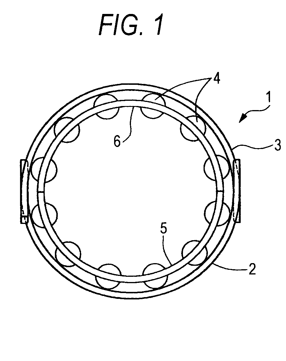
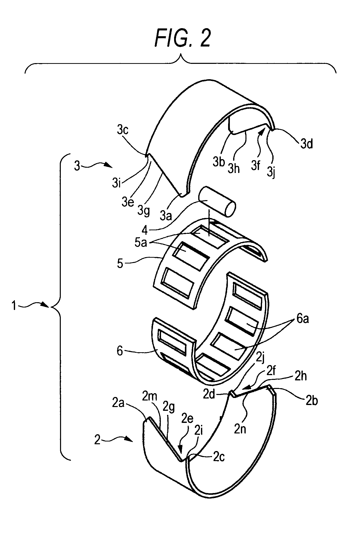
[0032]The best mode for carrying the invention is described by being shown in the accompanying drawings. A split rolling bearing is described by referring to FIGS. 1 and 2. FIG. 1 is a side view illustrating a split rolling bearing. FIG. 2 is an exploded perspective view illustrating the split rolling bearing.

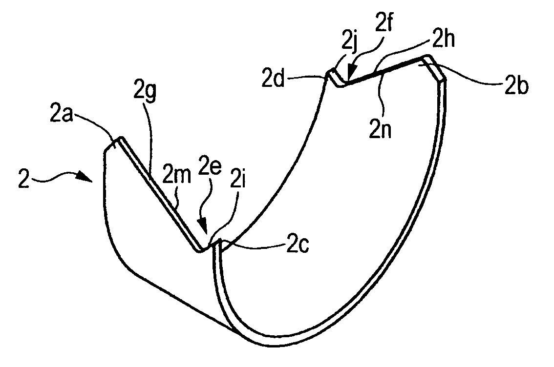
[0033]A rolling bearing 1 shown in the figures has paired split outer races 2 and 3, plural rollers 4 circumscribed on the inner surfaces of the paired split outer races 2 and 3, and paired split cages 5 and 6 for holding the rollers 4 arranged in such a way as to be substantially equally spaced in a circumferential direction thereof. The rollers 4 are inseparably accommodated in pockets 5a and 6a of the cages 5 and 6.

[0034]The split rolling bearing 1 can be used in the connection portion between a crankshaft and a connecting rod of an automobile engine. Such a mode of use is described by being illustrated in FIG. 3. FIG. 3 is across-sectional view illustrating a state in which...


PUM


Abstract

The present invention provides a split outer race for use in a rolling bearing. The split outer race is formed by bending a strip-shaped metallic plate into a substantially semicircle shape. At least one end of the split outer race in a circumferential direction has a concave-and-convex shape including a first slope portion which is inclined to an axial direction and a second slope portion inclined in a direction opposite to a direction in which the first slope portion is inclined. An edge portion formed on an inner surface of the one end in the circumferential direction has a round shape.

Description

BACKGROUND OF THE INVENTION[0001]The present invention relates to a split outer race, to a split rolling bearing using the split outer race, and to a manufacturing method for a split outer race. This split rolling bearing is used in a structure using a shaft as an inner race member, for example, in a connection portion between a crankshaft of an automobile engine and a large end part of a connecting rod thereof.[0002]For instance, a rolling bearing used in the connection portion between the crankshaft and the large end part of the connecting rod has paired split outer races, plural rollers circumscribed on the inner surfaces of the paired split outer races, and paired split cages for holding the rollers arranged in such a way as to be substantially equally spaced in a circumferential direction thereof. The split outer races are produced by using, for example, bearing steel to thereby manufacture a cylindrical outer race, and by thereafter splitting the cylindrical outer race into tw...

Claims


Application Information

Patent Timeline
Patent Type & Authority Patents(United States)
IPC IPC(8): F16C33/60B21D53/10F16C9/04F16C33/54F16C33/64
CPCF16C9/04F16C33/60F16C33/64F16C33/516F16C2360/22
Inventor WASEDA, YOSHITAKA
Owner JTEKT CORP
Why Eureka
Try Eureka