Cage for ball bearing

a ball bearing and cage technology, applied in the direction of shafts and bearings, rotary bearings, rolling contact bearings, etc., can solve the problems of abrasion and noise, inconvenience as described above, and the cage becomes likely to warp, so as to prevent abrasion or noise.

Inactive Publication Date: 2006-01-12
JTEKT CORP
View PDF13 Cites 21 Cited by
  • Summary
  • Abstract
  • Description
  • Claims
  • Application Information

AI Technical Summary

Benefits of technology

[0006] An object of this invention is to provide a cage for a ball bearing which can suppress or prevent its interference for a bearing ring member such as an outer ring or inner ring and so suppress or prevent abrasion or noise.
[0007] This invention is a cage of synthetic resin for a ball bearing having cage pockets for ball accommodation which are through holes which penetrate through a radial direction at a plurality of positions of a circumference, characterized in that on opposing edges of an outer circumferential opening of each of some of cage pockets, guiding faces for limiting the inward displacement in the radial direction of each of balls for a pitch circle diameter are provided; and on opposing edges of the inner circumferential opening of each of remaining cage pockets, guiding faces for limiting the outward displacement in the radial direction of each of the balls for the pitch circle diameter are provided, thereby making a ball guide.
[0008] In accordance with the cage according to this invention, since allowable inward and outward displacements of the cage are limited while making a ball guide, interference of the cage with a bearing ring member such as an outer ring or an inner ring can be suppressed or prevented. Particularly, where the rigidity of the cage is lowered by for example, making the cage with a large diameter, if the lead / lag of the balls occurs, the circumferential pulling stress or contractive stress acts on the cage so that the cage is likely to be elastically deformed inward or outward in the radial direction. Where the pulling stress circumferentially acts on the cage, the outer circumferential faces of the cage interfere with the ball so that the inward elastic deformation in the radial direction of the cage is suppressed. Where the contractive stress circumferentially acts on the cage, the inner circumferential faces of the cage interfere with the ball so that the outward elastic deformation in the radial direction of the cage is suppressed. Thus, the interference of the cage with the bearing ring member such as the outer ring or inner ring is suppressed or prevented.
[0010] Preferably, stoppers for stopping the come-off of the balls are provided at the inner circumferential opening of each of some of cage pockets with the guiding faces provided on the outer circumferential opening, and at the outer circumferential opening of each of the remaining cage pockets with the guiding faces provided on the inner circumferential opening. In accordance with this configuration, since the balls can be held non-separately in the cage pockets, the cage can be easily handled.
[0011] Preferably, the outer circumferential guiding faces and the inner circumferential guiding faces are alternately provided at every predetermined number of cage pockets along the circumference. This configuration is useful to prevent the interference of the cage with the bearing ring member such as the outer ring or inner ring.
[0021] In accordance with the cage for a ball bearing according to this invention, the cage can be made difficult to interfere with the bearing ring member, thereby preventing or suppressing occurrence of abrasion or noise. This contributes to reduction of bearing torque.

Problems solved by technology

Therefore, the rigidity is lowered so that the cage becomes likely to warp.
This leads to occurrence of abrasion and noise.
In this case also, the inconvenience as described above occurs.

Method used


Image

  • Cage for ball bearing
  • Cage for ball bearing
  • Cage for ball bearing

Examples


Embodiment Construction

[0031] Now referring to the drawings, an explanation will be given of the best mode of this invention.

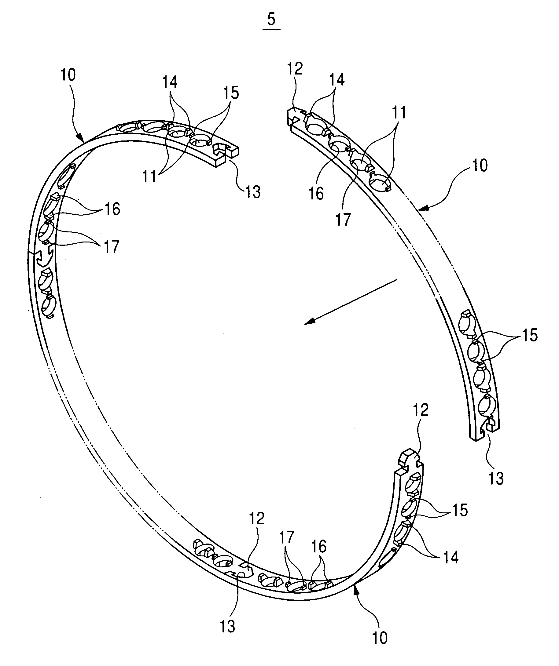
[0032] First, referring to FIG. 9, an explanation will be given of the ball bearing using the cage according to this invention. It is assumed that the ball bearing is a slant-contact ball bearing. The ball bearing includes an outer ring 2, an inner ring 3, a plurality of balls 4 and a cage 5. Between the outer ring 2 and inner ring 3 which are opposite, lubricant such as grease is inserted.

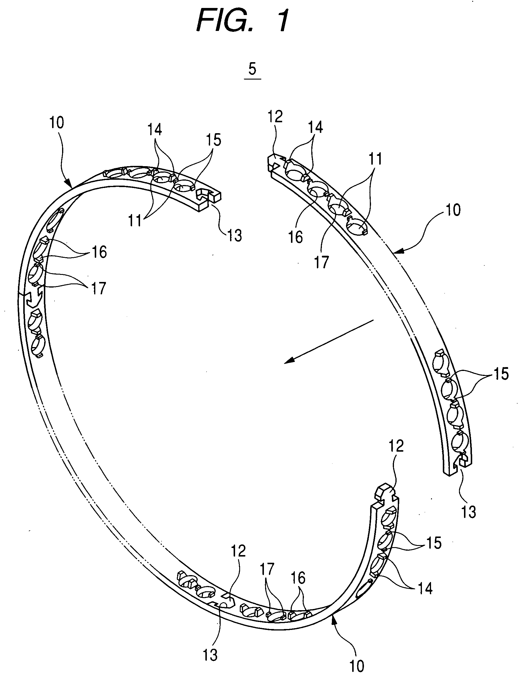
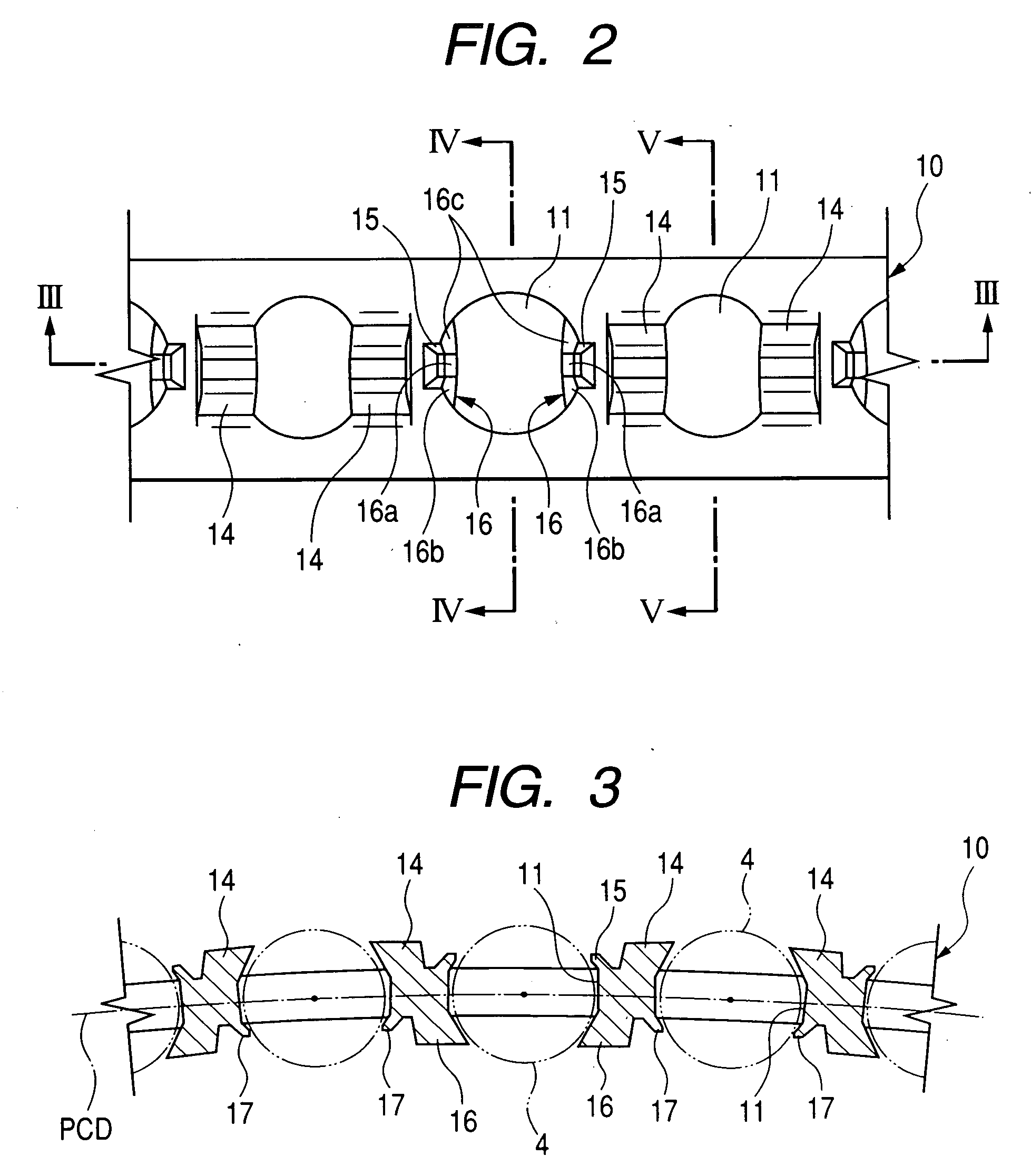
[0033] Referring to FIGS. 1 to 6, the cage 5 will be explained in detail. FIG. 1 is an exploded perspective view showing the best mode of the cage for a ball bearing according to this invention. FIG. 2 is a planar developed view of the cage. FIG. 3 is a view taken by an arrow of line III-III in FIG. 2. FIG. 4 is a view taken by an arrow of line IV-IV in FIG. 2. FIG. 5 is a view taken by an arrow of line V-V in FIG. 2. FIG. 6 is a partially enlarged view of FIG. 3.

[0034] The cage 5 (or cage body...


PUM


Abstract

In the cage, on opposing edges of an outer circumferential opening of each of some of cage pockets, guiding faces for limiting the inward displacement in the radial direction of each of balls for a pitch circle diameter are provided; and on opposing edges of the inner circumferential opening of each of remaining cage pockets, guiding faces for limiting the outward displacement in the radial direction of each of the balls for the pitch circle diameter are provided, thereby making a ball guide.

Description

BACKGROUND OF THE INVENTION [0001] 1. Field of the Invention [0002] This invention relates to a cage for a ball bearing serving as a ball guide. This cage is preferably used for, for example, a ball bearing for a revolving seat which supports the rotary segment of a CT scanner. [0003] 2. Related Art [0004] For example, in a ball bearing for a revolving seat having a large diameter, where a cage in the same type as a cylindrical cage used for a ball bearing for a general machine tool is adopted (e.g. see JP-A-2004-60775), the thickness of the cage becomes very thin relatively to the diameter thereof. Therefore, the rigidity is lowered so that the cage becomes likely to warp. Where such a cage is used, if the lead / lag of the balls occurs, the region between adjacent cage pockets of the cage may be pulled circumferentially so that the cage is elastically deformed in a straight shape; or otherwise may be contracted so that the cage is elastically deformed in a warped shape. Where such a...

Claims


Application Information

Patent Timeline
Patent Type & Authority Applications(United States)
IPC IPC(8): F16C33/38
CPCF16C33/3856F16C33/3812F16C19/163F16C2316/10F16C2300/14
Inventor SEKIMOTO, HIROSHIKOYAMA, AKIRA
Owner JTEKT CORP
Why Eureka
Try Eureka