Rotary shaft control apparatus

a technology of rotary shaft and control apparatus, which is applied in the direction of electric controllers, program control, instruments, etc., can solve the problems of rotating body vibrating, and achieve the effect of suppressing or preventing vibration

Inactive Publication Date: 2007-03-27
FANUC LTD
View PDF8 Cites 4 Cited by
  • Summary
  • Abstract
  • Description
  • Claims
  • Application Information

AI Technical Summary

Benefits of technology

[0006]It is an object of the present invention to suppress or prevent the vibration that can occur due to the intervention of a low-rigidity part between the detector and the rotating body.
[0010]As the torque acting on the rotary shaft is proportional to the angular acceleration, the vibration can be suppressed or prevented by detecting the angular acceleration and compensating the command value accordingly.

Problems solved by technology

However, in the control of an indexing table in a machine tool, for example, the rotating body may vibrate due to the presence of a low-rigidity part such as a joint connecting between the rotating body and the detector.

Method used


Image

  • Rotary shaft control apparatus
  • Rotary shaft control apparatus
  • Rotary shaft control apparatus

Examples


Embodiment Construction

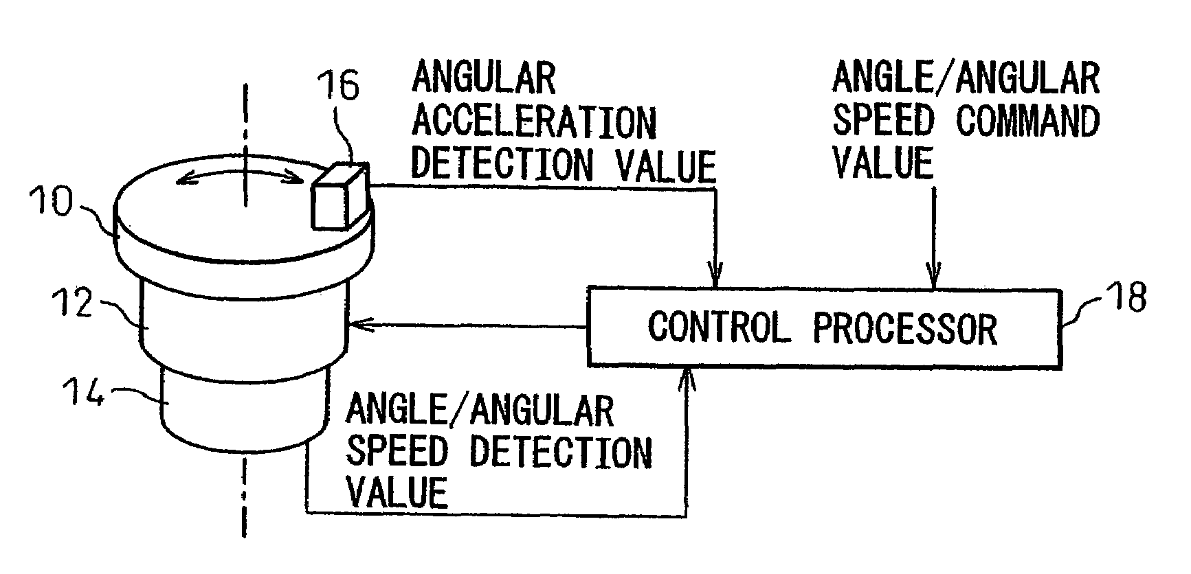
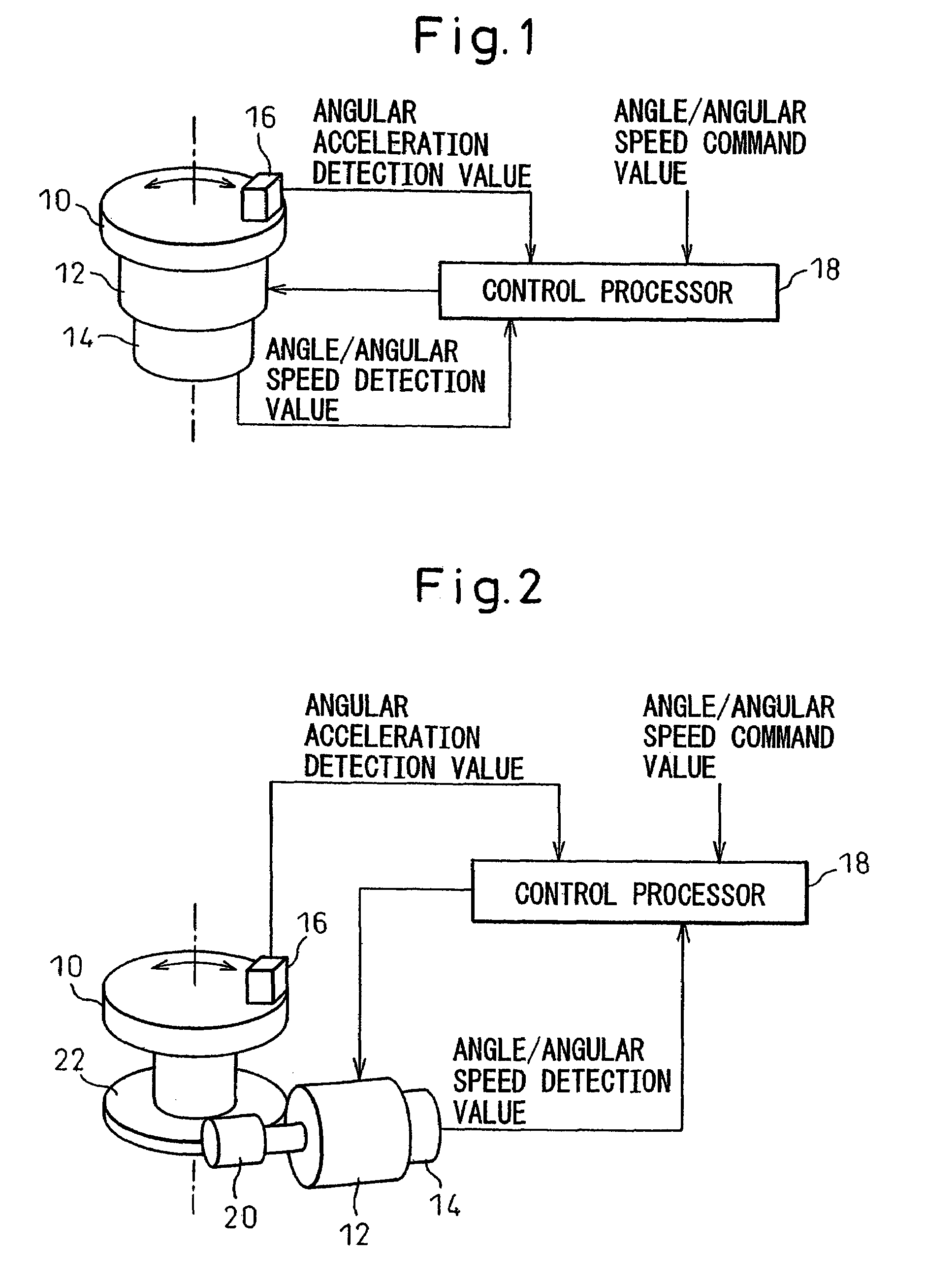
[0016]FIG. 1 shows one example of a rotary shaft control apparatus according to the present invention. This rotary shaft control apparatus is used, for example, to control an indexing table in a machine tool.

[0017]In FIG. 1, a rotating body 10 is connected to a servo motor 12 to which an angle / angular speed detector 14 such as an encoder is also connected. The angular speed is obtained, for example, from the time differentiation of the angle that the encoder outputs.

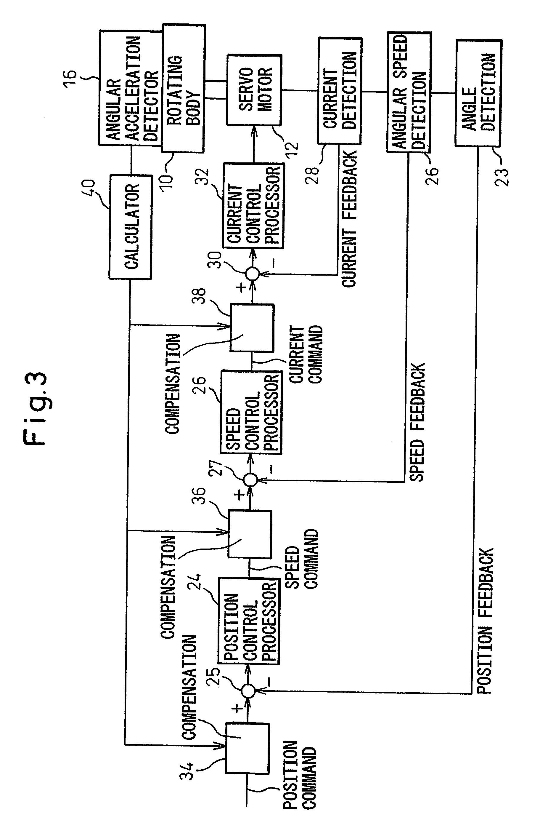
[0018]An angular acceleration sensor 16 for detecting the rotational angular acceleration of the rotating body 10 is mounted on the rotating body 10. A control processor 18 performs processing for compensating an angle / angular speed command value in accordance with an angular acceleration detection value fed from the angular acceleration sensor 16, in addition to the conventional processing for calculating an electric current control value for the servo motor 12 from the angle / angular speed command value and angle / angula...


PUM


Abstract

The invention aims to suppress or prevent the vibration that can occur due to the intervention of a low-rigidity part between detector and rotating body. An angular acceleration sensor for detecting the rotational angular acceleration of a rotating body is provided, and an angle / angular speed command value is compensated in accordance with the value of the angular acceleration.

Description

BACKGROUND OF THE INVENTION[0001]1. Field of the Invention[0002]The present invention relates to an apparatus for controlling a rotary shaft in a machine tool or the like.[0003]2. Description of the Related Art[0004]When controlling a rotary shaft in a machine tool, it is general practice to perform feedback control by detecting the rotational angle / rotational speed of a rotating body and by computing the amount of control of a servo motor from the difference between the detected angle / speed and its command value.[0005]However, in the control of an indexing table in a machine tool, for example, the rotating body may vibrate due to the presence of a low-rigidity part such as a joint connecting between the rotating body and the detector.SUMMARY OF THE INVENTION[0006]It is an object of the present invention to suppress or prevent the vibration that can occur due to the intervention of a low-rigidity part between the detector and the rotating body.[0007]According to the present inventio...

Claims


Application Information

Patent Timeline
Patent Type & Authority Patents(United States)
IPC IPC(8): G05B1/06
CPCG05B19/404G05B2219/37323
Inventor TANIGUCHI, MITSUYUKIIMAI, KEISUKE
Owner FANUC LTD
Why Eureka
Try Eureka