Energy storage system

a technology of energy storage and storage racks, applied in the direction of current conducting connections, cell components, electrochemical generators, etc., can solve the problems of electrical connection breaks between the trays and the racks, easy to damage,

Active Publication Date: 2014-12-02
SAMSUNG SDI CO LTD
View PDF22 Cites 14 Cited by
  • Summary
  • Abstract
  • Description
  • Claims
  • Application Information

AI Technical Summary

Benefits of technology

[0008]Aspects of embodiments of the present invention are directed toward an energy storage system including a connector unit installed in a rack to be connected to a tray and vibrating together when the tray vibrates due to, for example, an earthquake or external impact applied to the rack, thereby preventing an electric connection between the tray and the connector unit from being broken.
[0009]Aspects of embodiments of the present invention are directed toward an energy storage system including elastic members and an anchor installed in a rack to suppress or prevent vibrations due to, for example, an earthquake or external impact applied to the rack; thereby preventing an electric connection between the tray and the rack from being broken.
[0024]The rack may further include an anchor at an outer surface of the rack for securing the rack to an external surface and reducing the vibration applied to the rack.

Problems solved by technology

An issue with energy storage systems is that they are susceptible to damage caused by vibrations due to, for example, earthquakes or external impacts.
For example, vibrations can cause breaks in electrical connections between the trays and the rack.

Method used


Image

  • Energy storage system
  • Energy storage system
  • Energy storage system

Examples


Embodiment Construction

[0038]Hereinafter, embodiments according to the present invention will be described with reference to the accompanying drawings. Throughout the specification, the same reference numerals refer to the same elements. Here, when it is stated that one element is “connected” / “coupled” to another element, the one element may be directly connected / coupled to the other element, or may be indirectly connected / coupled to the other element via one or more intervening elements. Further, some of the elements that are not essential to the complete understanding of the invention are omitted for clarity.

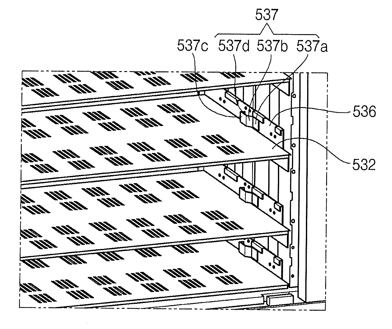
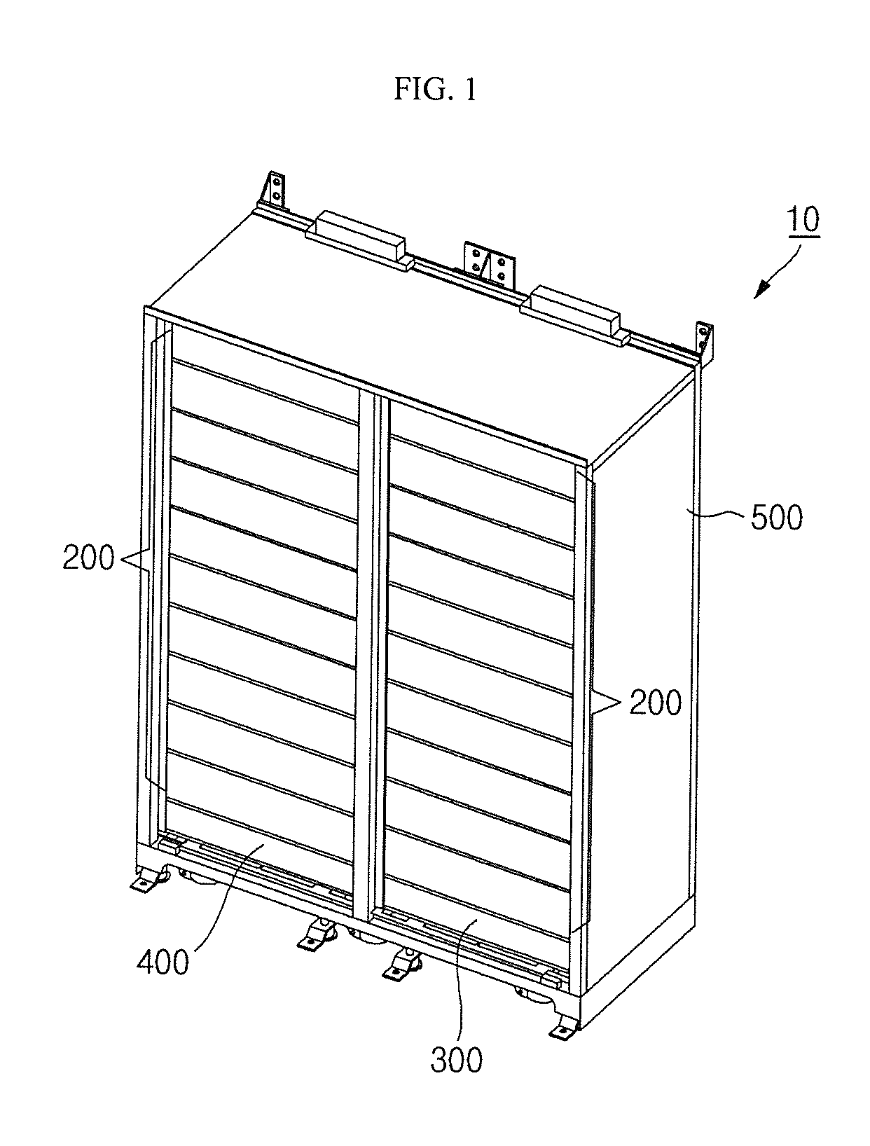
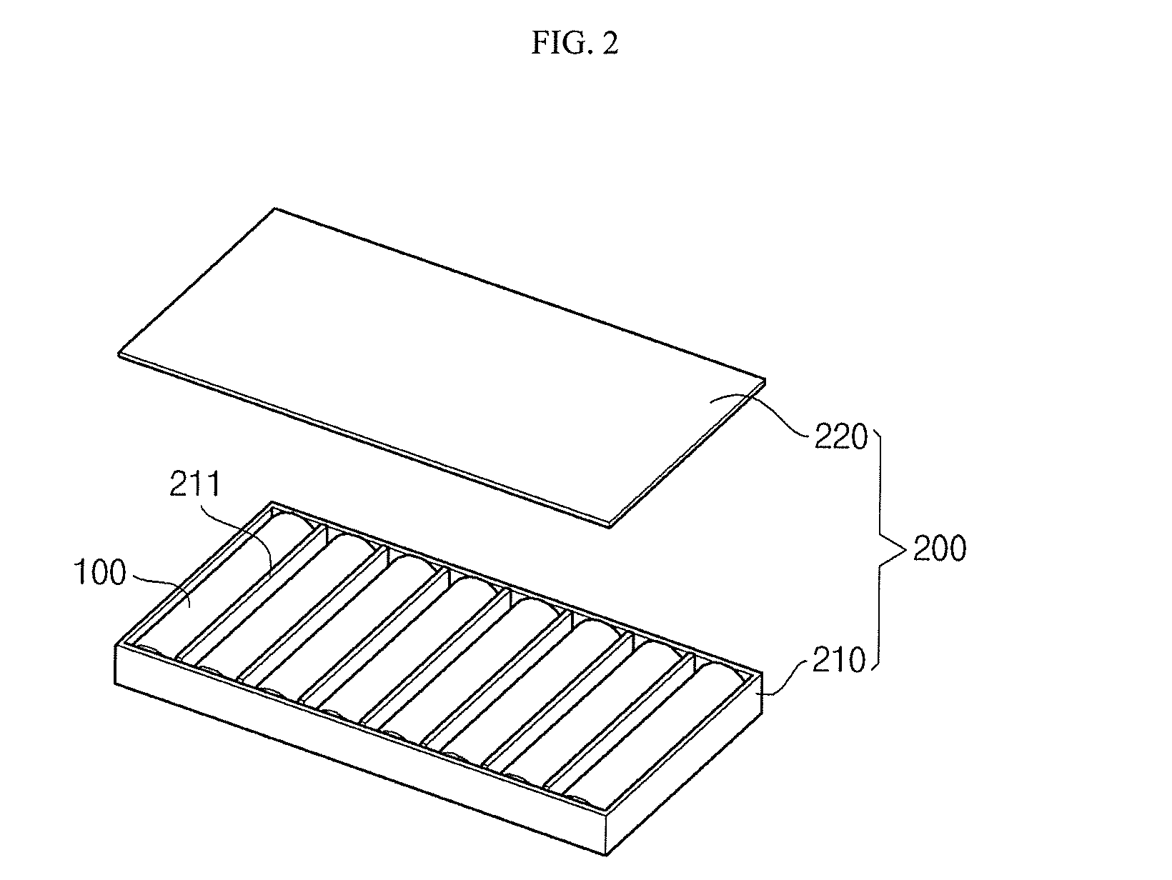
[0039]FIG. 1 is a perspective view of an energy storage system according to an embodiment of the present invention, and FIG. 2 is a perspective view of battery cells received in a tray shown in FIG. 1.

[0040]Referring to FIGS. 1 and 2, the energy storage system 10 according to an embodiment of the present invention includes a plurality of battery cells 100, a plurality of trays 200, a switch box 300,...


PUM

PropertyMeasurementUnit
diameteraaaaaaaaaa
size D2aaaaaaaaaa
size D2aaaaaaaaaa

Abstract

An energy storage system including a battery cell, a tray for receiving the battery cell, and a rack for receiving the tray. The rack includes a connector unit. The connector unit is configured to connect to the tray inserted into the rack and to vibrate together with the tray when the tray vibrates due to, for example, an earth quake or external impact applied to the rack, thereby preventing an electric connection between the tray and the connector unit from being broken.

Description

CROSS-REFERENCE TO RELATED APPLICATION[0001]This application claims the benefit of and priority to U.S. Provisional Application No. 61 / 532,292, filed on Sep. 8, 2011, in the United States Patent and Trademark Office, the disclosure of which is incorporated herein in its entirety by reference.BACKGROUND[0002]1. Field[0003]Embodiments of the present invention relate to an energy storage system.[0004]2. Description of Related Art[0005]An energy storage system may be linked with a renewable energy system, such as a solar cell, and may be configured to store power when electric power demand is low and to use the stored power at a time when electric power demand is high. For example, the energy storage system may be an energy storage device including a quantity of secondary batteries used in electronic devices, such as cellular phones or notebook computers.[0006]The secondary batteries may be received in a plurality of trays, which may be received in a plurality of racks, which may then b...

Claims


Application Information

Patent Timeline
Patent Type & Authority Patents(United States)
IPC IPC(8): H01M10/46H01M2/10H01M10/0525H01M50/209H01M50/211H01M50/213H01M50/262H01M50/289
CPCH01M10/465H01M10/0525H01M2/1016Y02E60/10H01M50/209H01M50/213H01M50/211H01M50/262H01M50/289H01M50/50H01M50/20
Inventor KIM, BYOUNGJUBYUN, JEONGDEOKKWAK, EUNOKYOON, JONGWOOK
Owner SAMSUNG SDI CO LTD
Why Eureka
Try Eureka