Stray field detector, magnetic disk drive, and method of head escaping

a detector and magnetic disk technology, applied in the direction of magnetic recording, magnetic disk recording, recording/reproducing/erasing methods, etc., can solve the problems of head not being able to escape, performance loss, incorrect detection of stray field, etc., to prevent the correct detection, and prevent the effect of demagnetization or degaussing of recorded magnetizations

Inactive Publication Date: 2007-10-30
HITACHI GLOBAL STORAGE TECH NETHERLANDS BV
View PDF7 Cites 10 Cited by
  • Summary
  • Abstract
  • Description
  • Claims
  • Application Information

AI Technical Summary

Benefits of technology

[0012]A feature of the present invention is to provide a reliable magnetic disk drive that prevents the demagnetization or degaussing of recorded magnetizations.
[0013]The magnetic disk drive according to an aspect of the present invention has the function that monitors the direct current components of the output from the read head, when the stray field is applied. In addition, it has the function that adaptively controls the field intensity at which the head starts the escape on the basis of the intensity variation in the stray field.
[0015]This makes it possible to prevent the write head from residing above the magnetic recording medium in the state that the stray field is applied, and to prevent the demagnetization or degaussing of recorded magnetizations. Moreover, to add a module that estimates the magnitude of the stray field on the basis of the variation in the direct current components of the output from the read head to the stray field detecting module as well as to escape the head on the basis of this estimation will make it possible to prevent the demagnetization or degaussing of recorded magnetizations, even in case there appears a sharp magnetic field variation.
[0016]According to the present invention, it is possible to correctly detect a stray field at the write head position in the circumstances that the stray field d is applied, to prevent the demagnetization or degaussing of recorded magnetizations, and to realize a highly reliable magnetic disk drive.

Problems solved by technology

The technique according to the patent document 1 and the patent document 2 cannot correctly detect the field intensity at the position of the write head, and if the stray field applied is not unique in the perpendicular direction to the recording medium at the position of setting the sensor and at the head position, the technique incorrectly detects the stray field.
This causes a performance loss by unnecessary escape, and if such a high stray field as the head should be escaped is applied, the head cannot be escaped, and the written signals are demagnetized or degaussed, which is the problem to be solved.
In addition, this technique detects the signal from the read head after passing a preamplifier and a read channel; since an auto gain control circuit and a base line correction circuit are generally located at the pre-stage of the A / D converter of the read channel, and the detection is made in the state that the signal from the read head is corrected, the technique cannot correctly detect the influence by the stray field.
Further, the preamplifier cannot sufficiently pass the direct current and low frequency components because these components are outside the pass band; therefore, this technique cannot achieve sufficient accuracy in detecting the stray field, which is the problem.
Although the technique can detect the stay field when the field increases extremely sharply, it causes demagnetization or degaussing during the performance of the head escape, which is the problem to be solved.
And, when there occurs a very steep magnetic field variation that the amplifier incorporated in the conventional HDD can detect, there is a possibility that causes demagnetization or degaussing during the performance of the head escape.
The technique according to the patent document 5 requires shielding with a member made of a soft magnetic material having a thickness greater than a certain thickness in order to attain a sufficient effect of magnetic shielding; therefore, it is not necessarily possible to practically apply this technique especially to a mobile HDD in view of the restrictions of the weight and dimension.
In addition, since a thorough magnetic shielding is impossible in general, a magnetic shielding will attenuate the intensity of the stray field to some extent, but it is impossible to completely shut out the stray field.
In addition, in these techniques, the magnetic field applied increases with time, and if the increase rate of the field intensity is large, the magnetic field will exceed the field intensity that starts demagnetization during escape seek, thereby demagnetizing or degaussing the recorded magnetizations, which is the problem to be solved.

Method used


Image

  • Stray field detector, magnetic disk drive, and method of head escaping
  • Stray field detector, magnetic disk drive, and method of head escaping
  • Stray field detector, magnetic disk drive, and method of head escaping

Examples


first embodiment

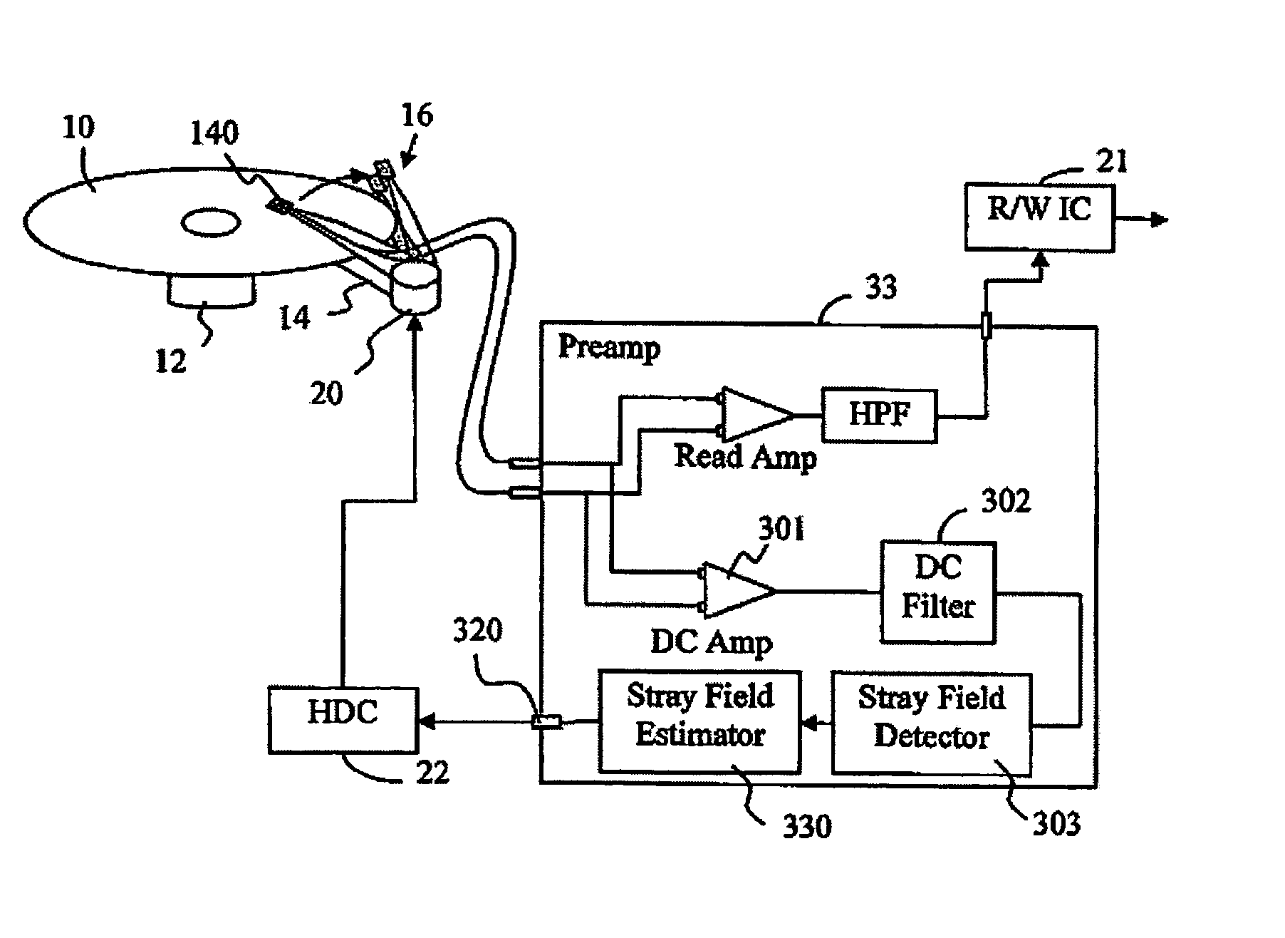
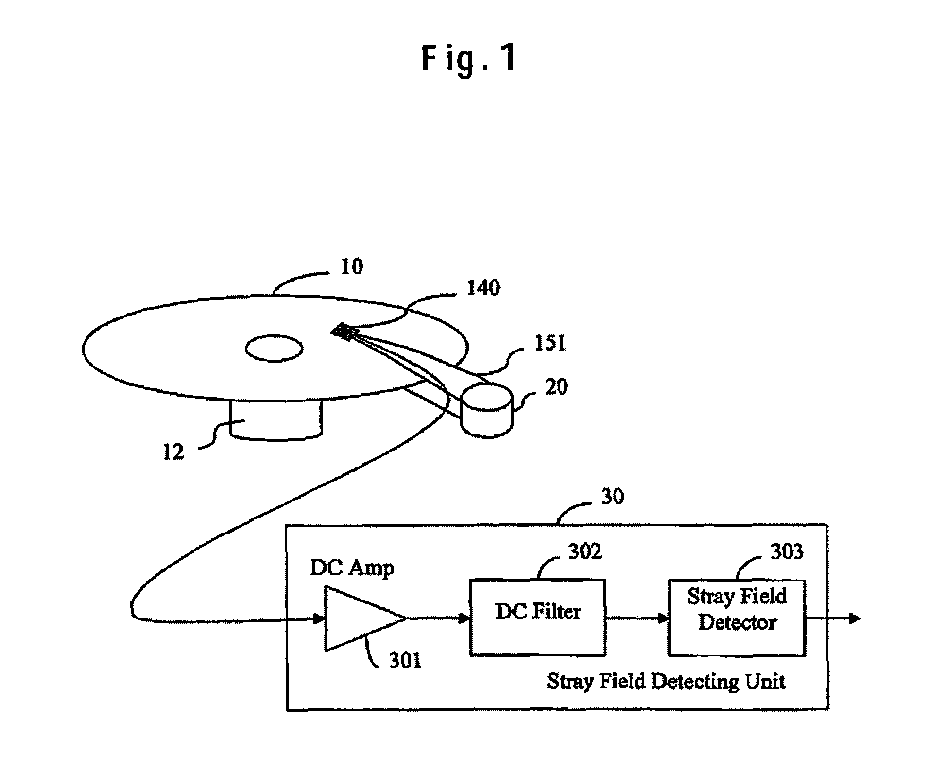
[0034]The embodiments of the present invention will be described with an application to a perpendicular magnetic disk drive. The stray field detecting method being the present invention will be described with reference to FIG. 1 and FIG. 2. The magnetic disk drive as shown in FIG. 1 includes a magnetic recording medium 10 that is driven to rotate by a motor 12, a head 140 that performs reading / writing to the magnetic recording medium 10, and a stray field detecting unit 30. The magnetic recording medium 10 is a double-layer perpendicular recording medium that has a magnetic recording layer and a soft under layer. The head 140 includes a single pole type head having a main pole and a return pole as the write head, and an MR element using a magneto-resistive effect such as the giant magneto-resistive effect and the tunneling magneto-resistive effect as the read head. The head 140 is mounted on a slider on the front of a suspension 151, and is positioned at a desired track on the magne...

second embodiment

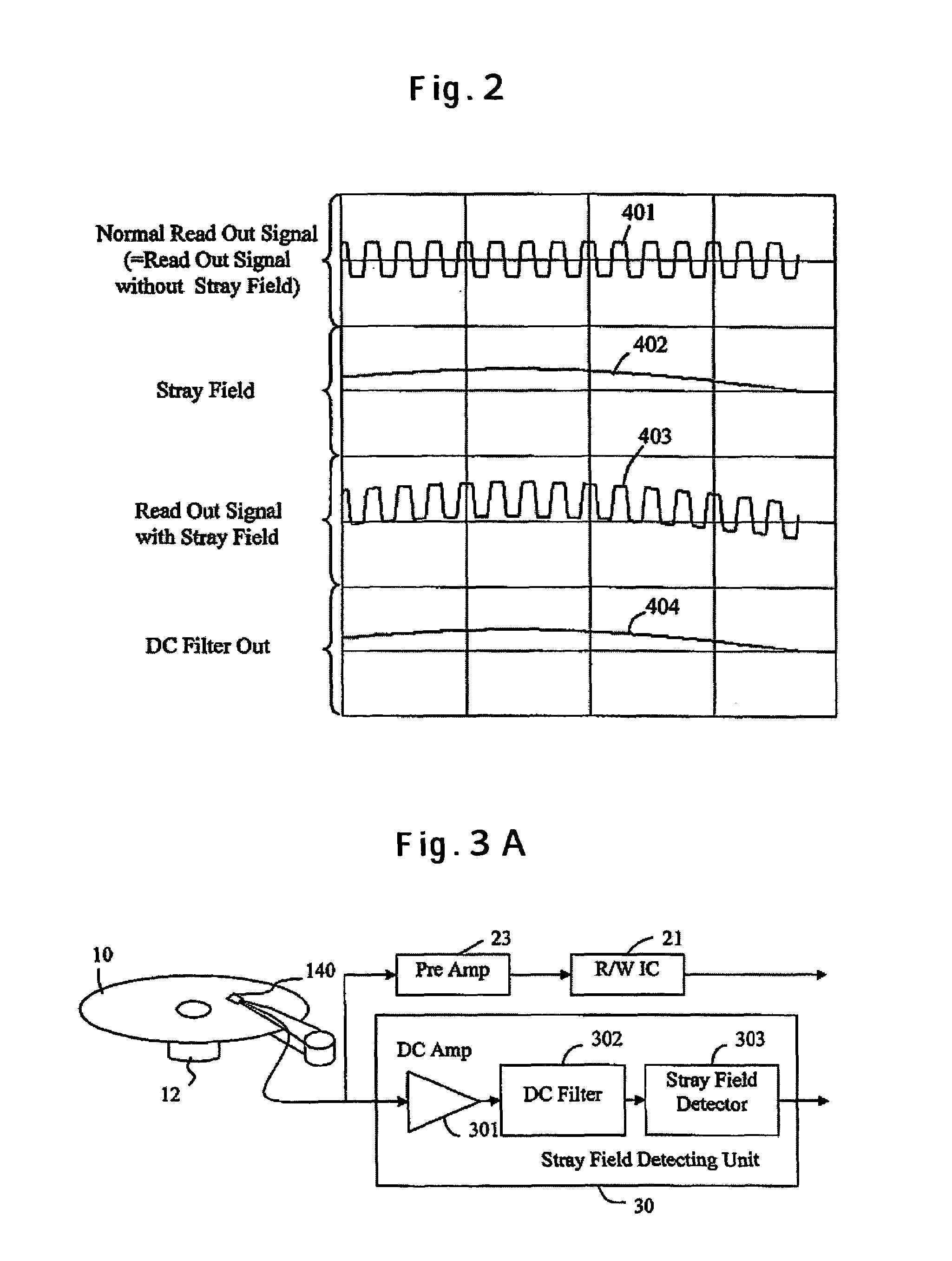
[0038]FIG. 3A trough FIG. 3C illustrate constructions of the magnetic disk drive including the stray field detector being the present invention. FIG. 3A illustrates a construction that adds the stray field detecting unit 30 to the conventional signal processing circuit. The readout signal from the head 140 having the MR element is sent to a preamplifier 23 being the conventional signal processing circuit and an R / W IC 21, and so forth. In parallel to this, the readout signal from the head 140 is sent to the stray field detecting unit 30. Inside the stray field detecting unit 30, the output signal from the MR element is inputted to the DC Amp 301 in the same manner as the case with FIG. 1. The DC Amp 301 amplifies the signal containing the direct current and low frequency components, and the DC filter 302 passes only the amplified signal containing the direct current and low frequency components. The stray field detector 303 detects a stray field from this signal containing the direc...

third embodiment

[0042]Next, the third embodiment relates the signal outputted from the stray field detector. The stray field detector 303 detects the stray field intensity from the output of the DC filter 302. The stray field detector 303 is able to output the detected stray field intensity as it is.

[0043]It is also possible to set in a memory a threshold determined in advance from the direct current and low frequency signal of the MR output in the state that the stray field is not applied, and when the stray field exceeds the threshold, to send out from the stray field detector 303 a signal showing that a critical stray field to cause demagnetization or degaussing is applied. It is possible to uniquely determine this threshold by the combination of the head and magnetic recording medium; however, since the resistance of the MR element varies depending on the temperature, it may be arranged to set several thresholds based on the relation between the temperature inside the drive, the operation time,...


PUM

PropertyMeasurementUnit
residual magnetic flux densityaaaaaaaaaa
lengthaaaaaaaaaa
speedaaaaaaaaaa

Abstract

Embodiments of the invention prevent demagnetization or degaussing of recorded magnetizations, even if a stray field is applied. In one embodiment, an output of a read head including a magneto-resistive effect element is inputted to a stray field detector through a DC amplifier and a DC filter. The stray field detector monitors dc components of the output from the read head, and escapes a head from above a magnetic recording medium.

Description

CROSS-REFERENCES TO RELATED APPLICATIONS[0001]This application claims priority from Japanese Patent Application No. JP2004-226319, filed Aug. 3, 2004, the entire disclosure of which is incorporated herein by reference.BACKGROUND OF THE INVENTION[0002]The present invention relates to a stray field detecting method, a stray field detector, and a stray-field-resistant magnetic disk drive in the data read / write device that magnetically reads a signal written in the thickness direction of a recording medium.[0003]The conventional recording technique will be described with a perpendicular magnetic disk drive as an example referring to FIG. 14 and FIG. 15. The perpendicular magnetic disk drive is a magnetic disk drive that possesses a perpendicular magnetic recording medium, a read / write head and so forth, and performs reading / writing by the perpendicular magnetic recording system. The perpendicular magnetic recording system, unlike the conventional longitudinal recording system, forms mag...

Claims


Application Information

Patent Timeline
Patent Type & Authority Patents(United States)
IPC IPC(8): G11B5/02
CPCG11B5/012G11B5/02G11B5/1278G11B27/36G11B2220/20G11B2005/0016G11B2005/0029G11B5/3903
Inventor ARAI, REIKOHAMAGUCHI, TAKEHIKOKIKUGAWA, ATSUSHIMAEDA, HIDEAKISHEN, LIPINGSUZUKI, MIKIO
Owner HITACHI GLOBAL STORAGE TECH NETHERLANDS BV
Why Eureka
Try Eureka