Vacuum cleaner

Inactive Publication Date: 2007-12-11
PANASONIC CORP
View PDF8 Cites 4 Cited by
  • Summary
  • Abstract
  • Description
  • Claims
  • Application Information

AI Technical Summary

Benefits of technology

[0006]In the present invention, the dirt particles suctioned are separated in two stages, thereb

Problems solved by technology

In such conventional arrangements, the dirt particles collected via air inlet 142 in dirt collecting chamber 141 a

Method used


Image

  • Vacuum cleaner
  • Vacuum cleaner
  • Vacuum cleaner

Examples


Embodiment Construction

[0035]A first preferred embodiment of the present invention will now be described with reference to FIGS. 1 to 12.

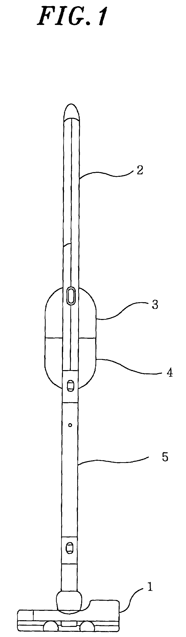
[0036]FIG. 1 is a front view of a vacuum cleaner in accordance with the first preferred embodiment of the present invention.

[0037]The vacuum cleaner includes suction inlet unit 1 through which dirt particles on a floor are suctioned; handle member 2 having a grip portion; electric blower chamber 3 incorporating therein an electric blower for generating a suction air stream, electric blower chamber 3 being attached to handle member 2; dirt separation and accumulation unit 4 detachably secured to a bottom portion of electric blower chamber 3; and extension tube 5 having a suction passage for allowing dirt separation and accumulation unit 4 to communicate with suction inlet unit 1, extension tube 5 connecting suction inlet unit 1 to handle member 2. Provided in handle member 2 is an exhaust port (not shown) for discharging dirt particles passing through an interior of exten...


PUM

PropertyMeasurementUnit
Centrifugal forceaaaaaaaaaa
Sizeaaaaaaaaaa
Densityaaaaaaaaaa

Abstract

A vacuum cleaner includes a first dirt separation unit and a second dirt separation unit. The first dirt separation unit has a first inlet port through which a suction air stream including dirt particles is introduced thereinto, and the second dirt separation unit has a second inlet port through which the air stream introduced into the first dirt separation unit is introduced into the second dirt separation. The first and the second inlet port are disposed such that they are not registered with each other. Accordingly, the dirt particles suctioned are separated in two stages, thereby decreasing the possibility of occlusion of a filter and rapid deterioration of a suction force.

Description

FIELD OF THE INVENTION[0001]The present invention relates to a vacuum cleaner; and, more particularly, to a vacuum cleaner including a structure for collecting dirt particles.BACKGROUND OF THE INVENTION[0002]Referring to FIG. 26, there is illustrated a conventional vacuum cleaner including dirt collecting chamber 141 with a bottom, and air inlet 142 provided in a side wall of dirt collecting chamber 141. A dirt-entrained air stream is tangentially introduced through air inlet 142 into dirt collecting chamber 141. Cover 144 is provided to cover upper opening 143 of dirt collecting chamber 141 and air outlet 145 is formed in cover 144. Further, there is provided filter 146 such that it covers upper opening 143 of dirt collecting chamber 141. Upon operation of the vacuum cleaner, dirt particles are suctioned from suction port 148 and collected through air inlet 142 in dirt collecting chamber 141. The collected dirt particles are centrifugally separated in dirt collecting chamber 141 an...

Claims


Application Information

Patent Timeline
IPC IPC(8): B01D45/12A47L9/10A47L9/16
CPCA47L9/102A47L9/1683A47L9/1633Y10S55/03
Inventor KUROKI, YOSHIKIYAMAGUCHI, SEIJIKATO, TOMONORIOKUSHIMA, MASASHISHIMIZU, YUICHIMITANI, TOMOMIMORIODACHI, TORUONISHI, YOSHIAKIKITAMURA, HIDENORIMIYAHARA, TOSHIFUMIOGAWA, TAKAAKINAGAOKA, HIROKAZU
Owner PANASONIC CORP
Why Eureka
Try Eureka