Optical CDMA transmitting apparatus and method for transmitting bipolar data

a technology of optical cdma and transmitting apparatus, applied in the field of optical cdma transmission apparatus and method for transmitting bipolar data, can solve the problems of dropping the data transmission rate, complex structure of the encoder for transmitting bipolar codes, etc., and achieve the effect of improving the transmission characteristics of optical cdma and minimizing the detrimental interferen

Inactive Publication Date: 2007-12-11
ELECTRONICS & TELECOMM RES INST
View PDF7 Cites 8 Cited by
  • Summary
  • Abstract
  • Description
  • Claims
  • Application Information

AI Technical Summary

Benefits of technology

[0005]It is another object of the present invention to provide an optical CDMA transmitting apparatus and method having a simple-structured optical CDMA encoder and an optical modulator, the apparatus and method which can improve the optical CDMA transmission characteristics by using modified pseudo-noise (PN) codes in the encoding process to minimize the detrimental interference between CDMA channels which is called multiple access interference. In accordance with an aspect of the present invention, there is provided an optical Code Division Multiple Access (CDMA) transmitting apparatus for transmitting bipolar data, including: an optical CDMA encoding unit for encoding a light from the outside into a code and a complement code of the code to generate an encoded light into the code and an encoded light into the complement code; and an optical modulation unit for selecting and transmitting one of the encoded lights into the code and the complement code of the code based on the polarity (‘0’ or ‘1’) of the data inputted from the outside.

Problems solved by technology

Moreover, the structure of the encoder for transmitting bipolar codes is complicated, and the use of an electric switch has dropped the data transmission rate.

Method used


Image

  • Optical CDMA transmitting apparatus and method for transmitting bipolar data
  • Optical CDMA transmitting apparatus and method for transmitting bipolar data
  • Optical CDMA transmitting apparatus and method for transmitting bipolar data

Examples


Embodiment Construction

[0020]Other objects and aspects of the invention will become apparent from the following description of the embodiments with reference to the accompanying drawings, which is set forth hereinafter.

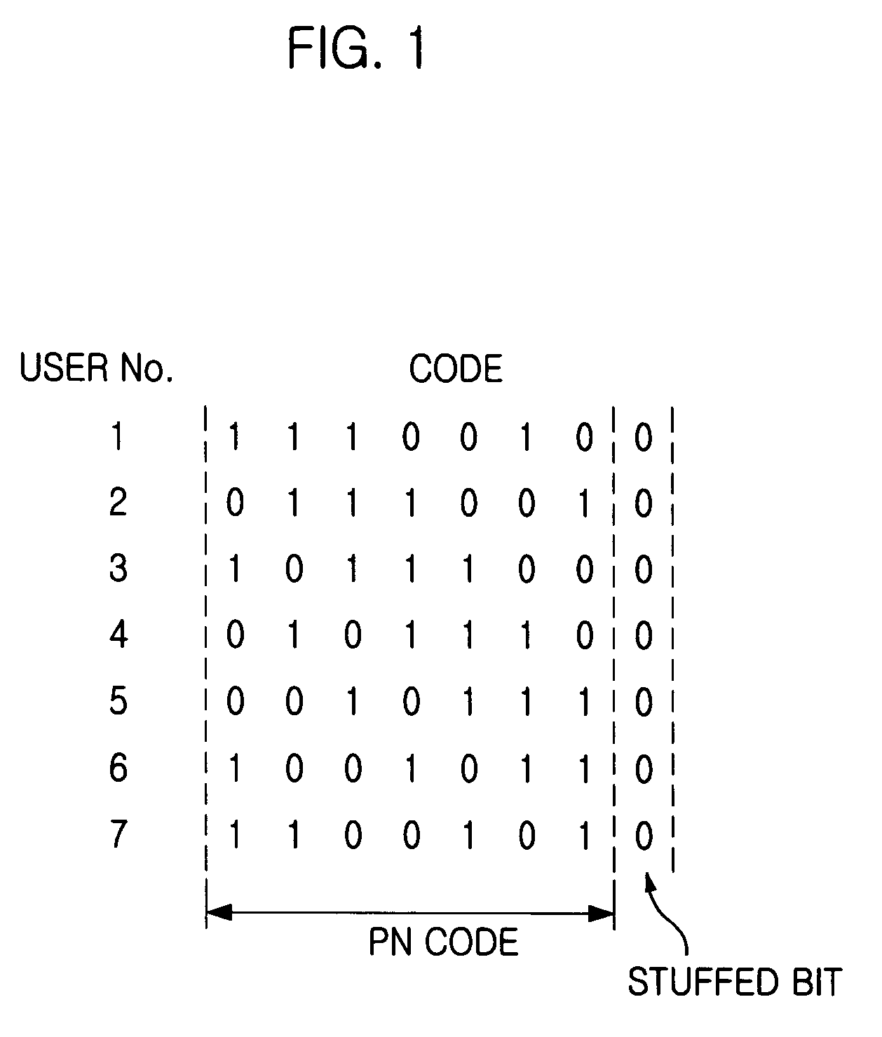
[0021]FIG. 1 is an exemplary diagram showing modified pseudo-noise (PN) codes in accordance with the present invention. In a conventional PN code, the number of ‘0’ and the number of ‘1’ are always different by one. Here, due to the difference between the number of ‘0’ and the number of ‘1’, interference occurs between the different Code Division Multiple Access (CDMA) channels in an optical CDMA system where bipolar data are transmitted and / or received using PN codes.

[0022]However, as illustrated in FIG. 1, the numbers of ‘0’ and ‘1’ can be the same by adding a stuffed bit ‘0’ to an arbitrary position of a PN code. Then, the interference between the different CDMA channels disappears in an optical CDMA system using bipolar data. Here, it does not matter where to put the stuffed bit in the ...


PUM


Abstract

Provided is an optical Code Division Multiple Access (CDMA) transmitting apparatus and method for transmitting bipolar data in an optical CDMA system. The optical CDMA transmitting apparatus and method of the present research has a simple structure, including only one optical CDMA encoder and one optical modulator. This technology minimizes multiple access interference by using modified pseudo-noise code in the encoding process, thus improving the optical CDMA transmission performance. The optical CDMA transmitting apparatus includes: an optical CDMA encoding means for encoding lights from the outside into a code or a complement code of the code; and an optical modulation means for transmitting the code or the complement code of the code which is selected in the optical CDMA encoding means based on the polarity (either ‘0’ or ‘1’) of the data inputted from the outside.

Description

FIELD OF THE INVENTION[0001]The present invention relates to an optical Code Division Multiple Access (CDMA) system; and, more particularly, to an optical CDMA transmitting apparatus and method for transmitting bipolar data in an optical CDMA system.DESCRIPTION OF RELATED ART[0002]Conventionally, the use of modified pseudo-noise (PN) codes have been limited to a temporal domain Code Division Multiple Access (CDMA) system, which uses electric signals in consideration of their electrical characteristics, and not used in a spectral domain.[0003]In conventional optical CDMA systems, an encoder uses two optical modulators and one electric switch to transmit bipolar data. If the data is ‘1’, the CDMA transmitting apparatus transmits PN codes or Walsh codes, or if the data is ‘0’, it transmits a complement code to the codes used when the data are ‘1’. Here, the modified PN code is not applied thereto. Moreover, the structure of the encoder for transmitting bipolar codes is complicated, and...

Claims


Application Information

Patent Timeline
Patent Type & Authority Patents(United States)
IPC IPC(8): H04J4/00H04B10/04H04B10/12H04J14/00H04J13/00
CPCH04J14/005H04J13/16H04B10/50H04B10/00
Inventor KIM, BONG KYUYEON, YOUNGHEEKIM, BYOUNG WHILEE, HYEONG HOPARK, SANGJO
Owner ELECTRONICS & TELECOMM RES INST
Why Eureka
Try Eureka