Antenna element for a radio device

a radio device and antenna technology, applied in the direction of resonant antennas, shielding materials radiating elements, substation equipment, etc., can solve the problems of limiting the design of the element, increasing the design difficulty of the antenna, and worse electrical characteristics, so as to reduce the production cost of the radio device and improve the antenna radiation characteristics

Active Publication Date: 2008-06-24
PULSE FINLAND
View PDF13 Cites 59 Cited by
  • Summary
  • Abstract
  • Description
  • Claims
  • Application Information

AI Technical Summary

Benefits of technology

[0008]An advantage of the invention is that a cover element of a radio device, which is required in any case, can be used as a radiator. Another advantage of the invention is that as the radiating element is relatively large and is located on the outer surface of the device, the radiation characteristics of the antenna are better than those of a radiator located more internally in the device. A further advantage of the invention is that the space reserved by the antenna within the device is smaller than in corresponding prior-art antennas. A further advantage of the invention is that it reduces the production costs of the radio device.

Problems solved by technology

This means that as the devices become smaller and smaller, the space available for the antenna becomes smaller, too, making antenna design even more challenging.
As mobile terminals become smaller in the direction of thickness, too, this distance inevitably becomes shorter, whereby the electrical characteristics become worse.
Particularly this problem concerns foldable mobile phone models, as their folding parts are relatively flat and thin.
A disadvantage of the element shown in FIG. 1 is that its parts have to have certain electrical sizes, which limits the design of the element.
Moreover, the characteristics of the antenna using the element may be inadequate in flat and thin radio devices.

Method used


Image

  • Antenna element for a radio device
  • Antenna element for a radio device
  • Antenna element for a radio device

Examples


Embodiment Construction

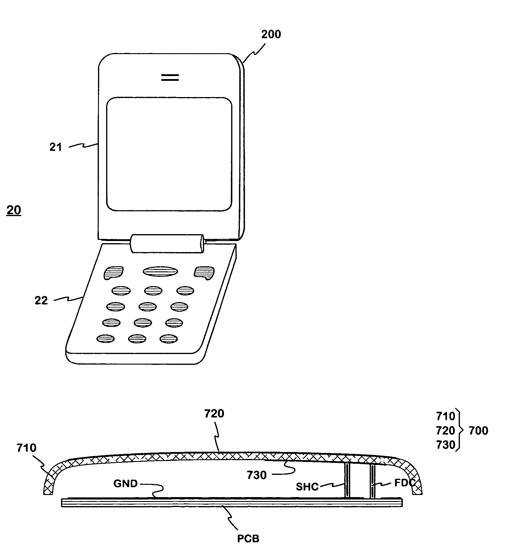
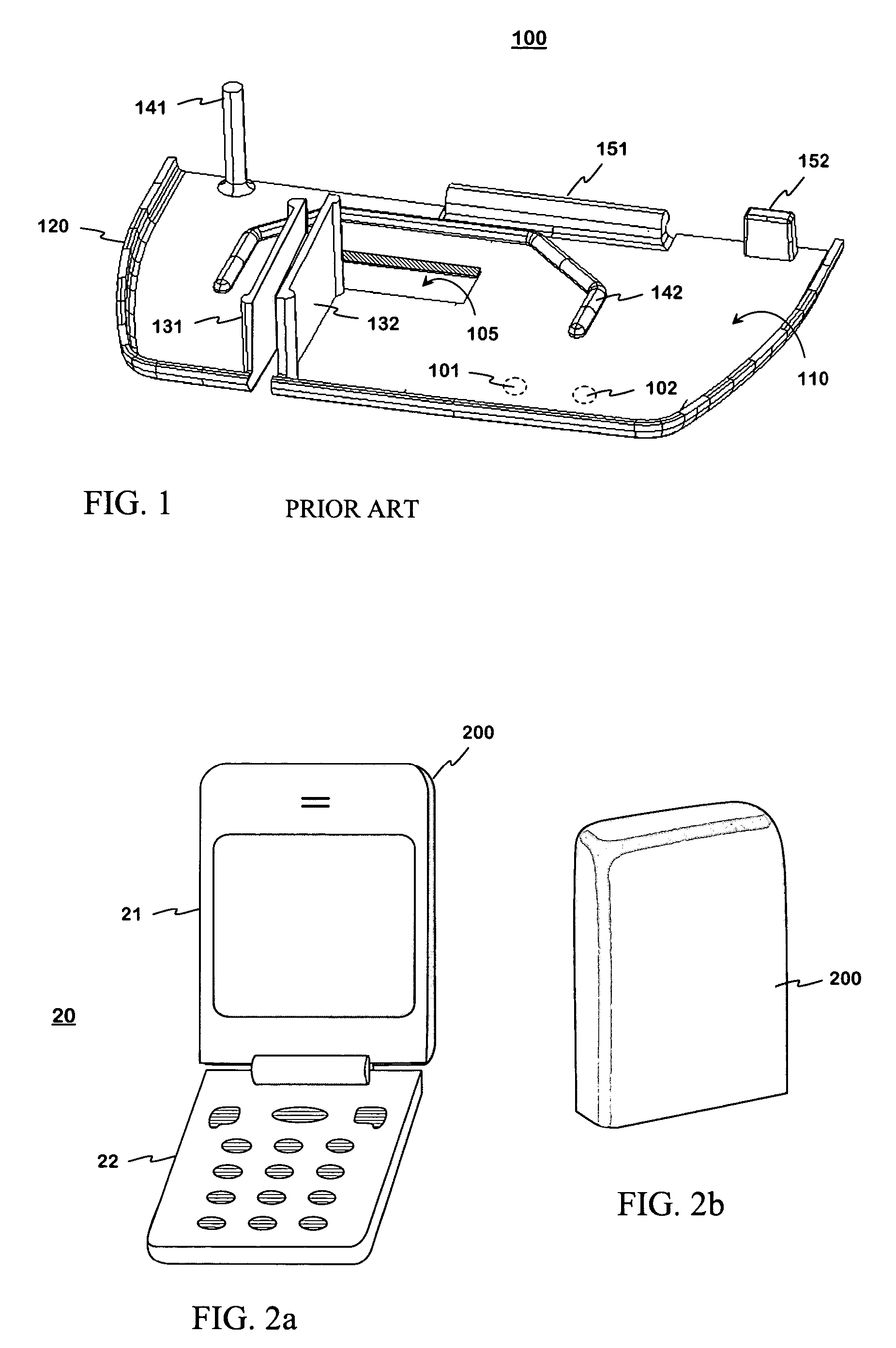
[0022]FIGS. 2a and 2b show an example of a radiating antenna element according to the invention. The antenna element 200 belongs to a radio device depicted in FIG. 2a which in this example is a foldable communication device 20. The communication device has a first part 21 and a second part 22 which can be turned with respect to one another around a hinge located between them. FIG. 2b shows just the antenna element 200. This is a single conductive piece constituting the back side and relatively narrow lateral sides and the upper end side of the cover of the first part 21. It may be made of aluminum by extruding, for example. The size of the antenna element is not bound to the wavelength corresponding to an operating frequency. The element is large compared to a quarter of the wavelength, enabling good radiation and receive characteristics. The location of the radiator on the outer surface of the radio device has the same effect. In the end product, the antenna element 200 as well as ...


PUM


Abstract

A radiating antenna element intended to be used in small-sized radio devices, and a radio device having an antenna element according to the invention. The antenna element is part of the covers of a radio device. The antenna element may be conductive throughout, or it may comprise a dielectric portion and a conductive portion, which constitute a single integral component. The radiating portion of the antenna element is relatively large, e.g. in a foldable phone (20) the antenna element (200) may comprise the whole cover of a foldable part (21) except for the front side. The radiating element is advantageously fed electromagnetically through a feed element. As the radiating element is relatively large and is located on the outer surface of the device, the radiation characteristics of the antenna are good, and the space required by the antenna inside the device is relatively small.

Description

[0001]The invention relates to a radiating antenna element intended to be used in small-sized radio devices in particular. The invention also relates to a radio device having an antenna element according to the invention.BACKGROUND OF THE INVENTION[0002]In antenna design, the space available is an important factor. It is relatively easy to make an antenna of good quality if there are no size limitations. In small-sized radio devices, such as mobile phones, an antenna which protrudes outside the covers of the device is tried to be avoided, for convenience. This means that as the devices become smaller and smaller, the space available for the antenna becomes smaller, too, making antenna design even more challenging.[0003]Internal antennas in mobile terminals usually have planar structures: The antenna comprises a radiating plane and a ground plane parallel thereto. The electrical characteristics of a planar antenna, such as bandwidth and antenna gain, depend on the distance between sa...

Claims


Application Information

Patent Timeline
Patent Type & Authority Patents(United States)
IPC IPC(8): H01Q1/24H01Q1/40H01Q1/38H01Q5/00H01Q5/371H01Q9/04H01Q19/00
CPCH01Q1/243H01Q1/38H01Q9/0414H01Q5/371H01Q9/0442H01Q9/0457H01Q19/005H01Q9/0421
Inventor MIKKOLA, JYRKIANNAMAA, PETTERIKALISTAJA, ESA
Owner PULSE FINLAND
Why Eureka
Try Eureka