Separation system with a sheath-flow supported electrochemical detector

a separation system and detector technology, applied in the field of chemical analysis systems and techniques, can solve the problems of large and expensive optical detection systems, potential shifts at the working electrodes of detectors, and the use of fluorescence-based detection methods that require large optical detection systems, etc., to achieve the effect of enhancing separation efficiency, reducing detection costs, and significantly increasing detector sensitivity

Inactive Publication Date: 2008-10-21
RGT UNIV OF CALIFORNIA
View PDF5 Cites 8 Cited by
  • Summary
  • Abstract
  • Description
  • Claims
  • Application Information

AI Technical Summary

Benefits of technology

[0019]The invention can include one or more of the following advantages. Electroactive analytes can be transported to an EC detector placed relatively far away from the end of a CE separation column. This provides decoupling of the CE electric field from the EC detector. As such, detector sensitivity is significantly increased while separation efficiency is enhanced. Larger separation channels and higher separation electric fields can also be used. Additionally, the EC detector is reliable and relatively easy to use.

Problems solved by technology

However, the fluorescence-based detection methods often employed require large and expensive optical detection systems.
An important issue when performing amperometric detection with CE is the necessary electrical isolation of the EC detector from the separation voltage, since interference from the CE current significantly influences detector performance.
However, since the grounded-end of the CE circuit is within the detection reservoir, the remaining electric field causes potential shifts at the working electrode of the detector.

Method used


Image

  • Separation system with a sheath-flow supported electrochemical detector
  • Separation system with a sheath-flow supported electrochemical detector
  • Separation system with a sheath-flow supported electrochemical detector

Examples


Embodiment Construction

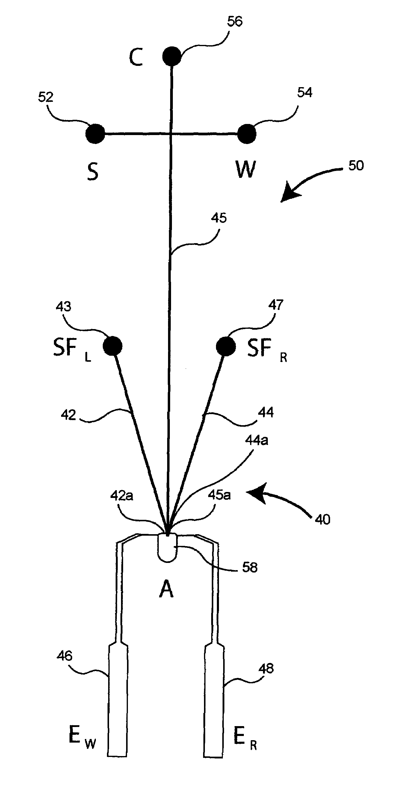
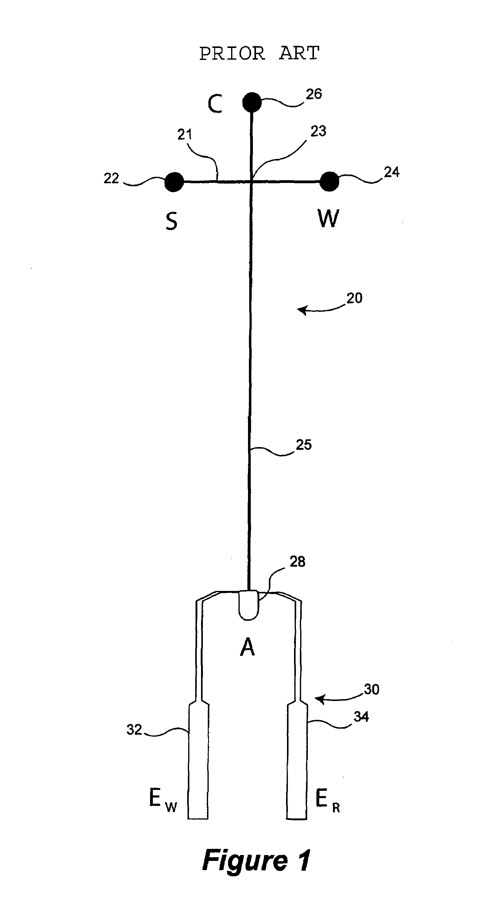
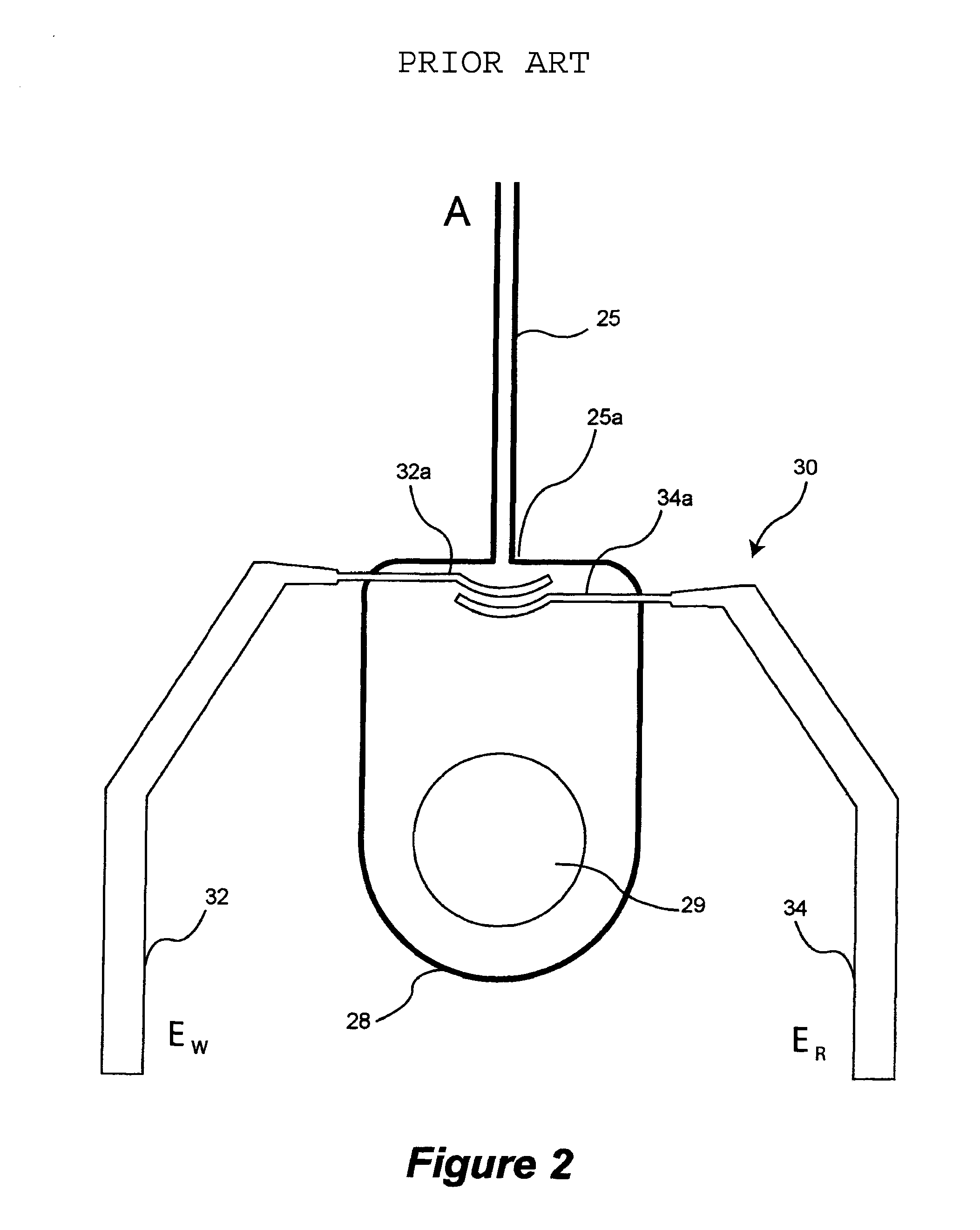
[0037]Reference will now be made in detail to some specific embodiments of the present invention including the best modes contemplated by the inventor for carrying out the invention. Examples of these specific embodiments are illustrated in the accompanying drawings. While the invention is described in conjunction with these specific embodiments, it will be understood that it is not intended to limit the invention to the described embodiments. On the contrary, it is intended to cover alternatives, modifications, and equivalents as may be included within the spirit and scope of the invention as defined by the appended claims.

[0038]In the following description, numerous specific details are set forth in order to provide a thorough understanding of the present invention. The present invention may be practiced without some or all of these specific details. In other instances, well known process operations have not been described in detail in order not to unnecessarily obscure the presen...


PUM

PropertyMeasurementUnit
angleaaaaaaaaaa
distanceaaaaaaaaaa
distanceaaaaaaaaaa

Abstract

An electrochemical detector including side channels associated with a separation channel of a sample component separation apparatus is provided. The side channels of the detector, in one configuration, provide a sheath-flow for an analyte exiting the separation channel which directs the analyte to the electrically developed electrochemical detector.

Description

CROSS REFERENCE TO RELATED APPLICATIONS[0001]This application claims priority under 35 U.S.C. 119(e) from Provisional U.S. Patent Application Ser. No. 60 / 563,917, filed Apr. 20, 2004, entitled “MICROFABRICATED SEPARATION SYSTEM WITH AN INTEGRATED SHEATH-FLOW-SUPPORTED ELECTROCHEMICAL DETECTOR”, which is incorporated herein by reference.STATEMENT REGARDING FEDERALLY SPONSORED RESEARCH[0002]The techniques and mechanisms of the present invention were made with Government support under NIH Grant No. HG01399 and Department of Energy Grant No. FG03-91ER61125.BACKGROUND[0003]1. Field of Invention[0004]The present invention relates to chemical analysis systems and techniques. In one example, the present invention relates to methods and apparatus for providing microfluidic electrochemical detection systems with increased sensitivity and reliability.[0005]2. Description of Related Art[0006]The miniaturization of chemical and biochemical analysis instrumentation has enabled the widespread use ...

Claims


Application Information

Patent Timeline
Patent Type & Authority Patents(United States)
IPC IPC(8): G01N27/447G01N27/453G01N27/27G01N27/49
CPCG01N27/44791
Inventor MATHIES, RICHARD A.EMRICH, CHARLES A.SINGHAL, PANKAJERTL, PETER
Owner RGT UNIV OF CALIFORNIA
Why Eureka
Try Eureka