
2x2 Mechanical optical switch

a mechanical and optical switch technology, applied in the field of optical switches, can solve the problems of high manufacturing cost, complicated and power-consuming, advantageous to the future development and popularity of the all-optical network system, etc., and achieve the effects of improving long-term stability, simple optical assembly, and new structural design

Active Publication Date: 2008-10-28
NAT TAIWAN UNIV
View PDF5 Cites 2 Cited by
  • Summary
  • Abstract
  • Description
  • Claims
  • Application Information

AI Technical Summary

Benefits of technology

The present invention is a mechanical optical switch with a novel structural design and a simple optical assembling process. It employs a long distance collimator for the assembly and alignment, which gives a longer working distance, lower manufacturing cost, and lower optical loss. The structural design features a mirror switch and a double-sided reflection ultra thin mirror, which can be easily assembled and aligned. The switch is manufactured using high precision technology and MEMS manufacturing process, reducing the misalignment and optical loss. The invention leverages the advantages of MEMS technology to overcome the drawbacks of conventional 2×2 optical switches. The switch has a lower manufacturing cost, lower optical loss, and lower misalignment. The invention can greatly lower the difficulty of the alignment and reduce the optical loss caused by lateral misalignment.

Problems solved by technology

This method is complicated and power-consuming, and thus it is not advantageous for the future development and popularity of the all-optical network system.
Since the dimensions of the optical switch manufactured by the all-MEMS process are very small, it is necessary to use a lens fiber (such as ball-lens fiber or taper lens fiber) for the assembling, and thus these switches incur a higher manufacturing cost, a very short working distance (approximately 100 microns to 300 microns), and a very serious lateral misalignment sensitivity.
For instance, a lens fiber such as a ball-lens fiber is used for assembling and alignment, which usually causes a misalignment of 1 μm and an optical loss of 1˜2 dB.
The 2×2 mechanical optical switch manufactured by the foregoing method achieves the functions of the 2×2 optical switch, but the thickness of the micro mirror produced in the micro mirror manufacturing process affects the alignment precision, and thus it is necessary to use a precise control mechanism to avoid optical loss due to inaccurate alignment.
However, a high precision control mechanism has the disadvantages of high cost and poor long-time stability, so that a high precision control mechanism is not advantageous to product commercialization and market competitiveness.

Method used


Image

  • 2x2 Mechanical optical switch
  • 2x2 Mechanical optical switch
  • 2x2 Mechanical optical switch

Examples


Embodiment Construction

[0020]To make it easier for our examiner to understand the objective, innovative features and performance of the present invention, we use preferred embodiments and the accompanying drawings for a detailed description of the present invention.

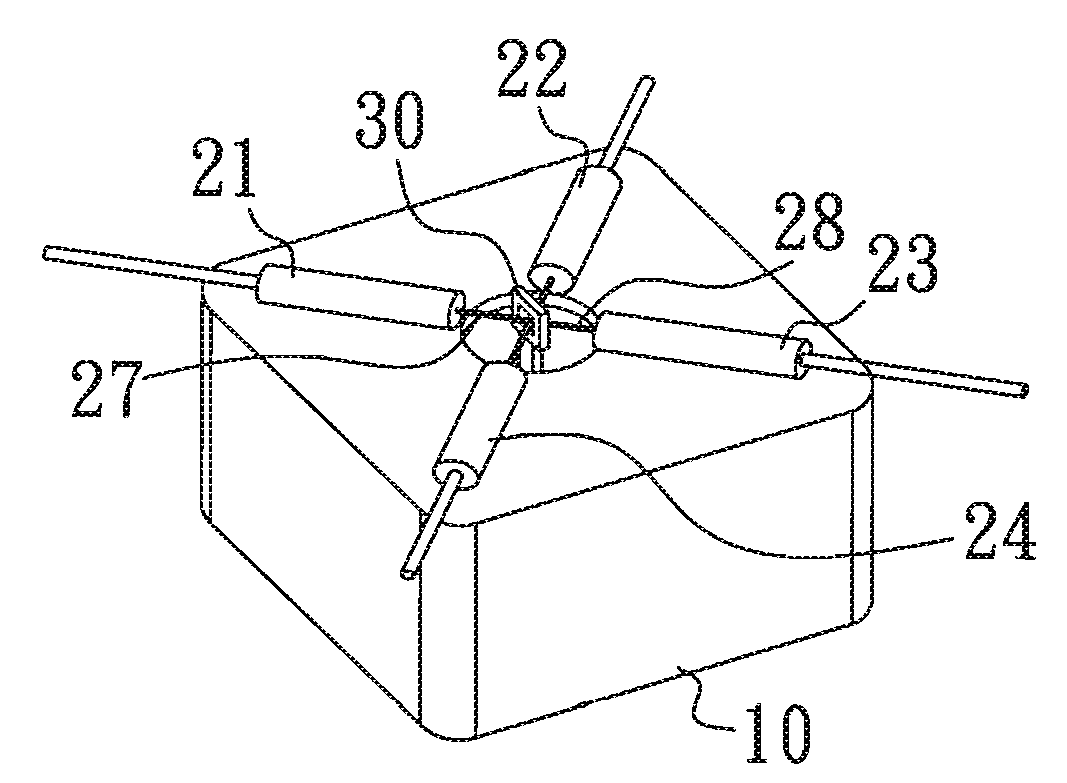
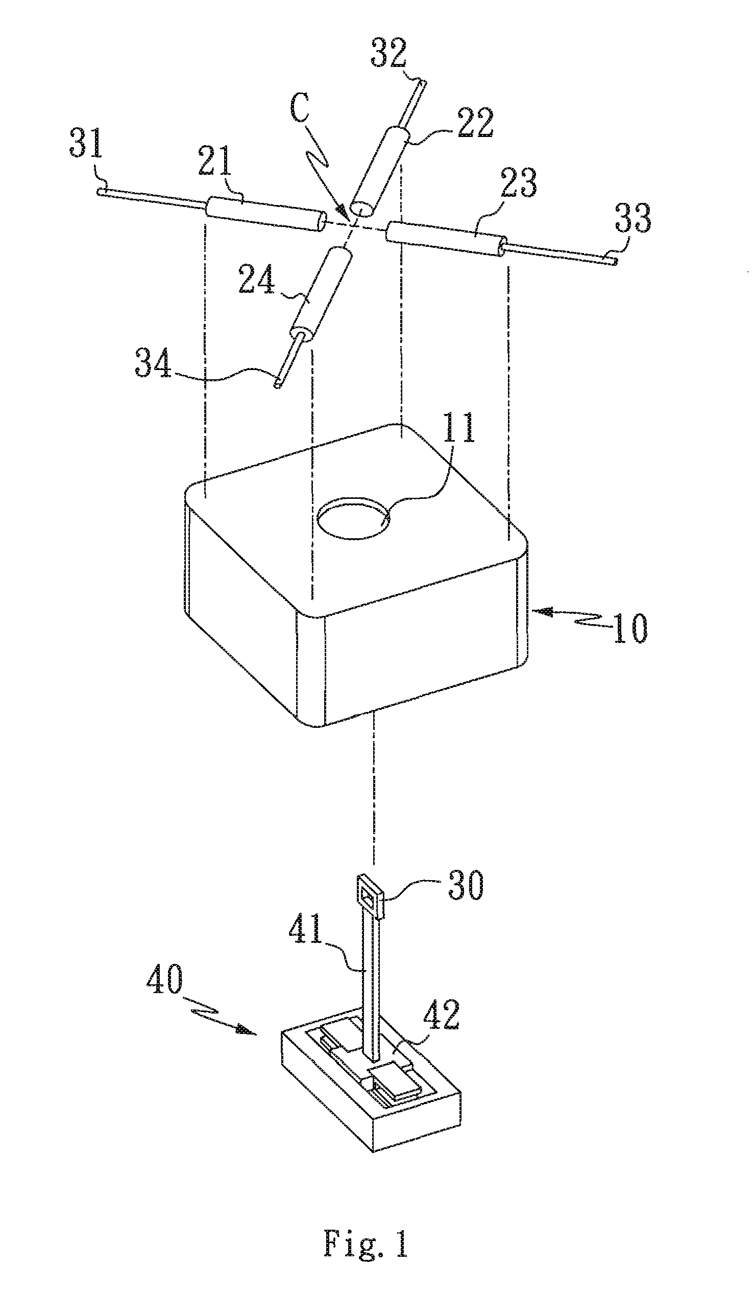
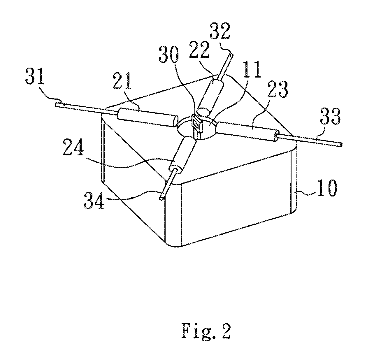
[0021]Referring to FIGS. 1 and 2 for an exploded view and a perspective view of a 2×2 mechanical optical switch in accordance with the present invention respectively, the 2×2 mechanical optical switch comprises a base 10, two input collimators 21, 22, two output collimators 23, 24, a double-sided reflection ultra thin mirror 30 and a mirror switch 40, wherein the collimators 21, 22, 23, 24 are coupled to optical fibers 31, 32, 33, 34 respectively, and the two input collimators 21, 22 and the two output collimators 23, 24 are installed on a common plane of the base 10, and the connection line of the input collimator 21 and the output collimator 23 is intersected with the connection line of the input collimator 22 and the output collimator 24 at ...


PUM


Abstract

A 2×2 mechanical optical switch includes a base, four collimators (two input collimators and two output collimators), an ultra thin mirror (double-sided reflection) and a switching mechanism of the mirror. This switch utilizes four collimators, which are arranged 90° with each other on a common plane, to emit and receive parallel light beams at a certain distance. The light beams are reflected by an ultra thin mirror. When the mirror is moved away from the intersection point of two optical paths, the input lights will directly enter into output channels (transmission state). While the mirror is moved to the intersection point which is the reflection position, the optical beams will be bent into alternate output channels (reflection state) simultaneously from both sides of the ultra thin mirror.

Description

FIELD OF THE INVENTION[0001]The present invention relates to an optical switch of an optical fiber communication system, and more particularly to an optical switch using a motive force of a mechanical component to drive a double-sided reflection ultra thin mirror for switching an optical path, and the optical switch can quickly cross connect or switch the transmission path of an optical signal and transmit the signal to a specific output optical fiber. In the meantime, the novel design and structure of the invention can achieve the automatic manufacturing and alignment of the optical switch easily and lower the manufacturing cost of the optical switch.BACKGROUND OF THE INVENTION[0002]Optical switch is one of the essential components of an all-optical network for performing a direct, cross, and multi-way switching transmission of optical signals in an optical fiber network system. In the past, a widely used optical switch generally converted an inputted optical signal into an electri...

Claims


Application Information

Patent Timeline
Patent Type & Authority Patents(United States)
IPC IPC(8): G02B6/26G02B6/42
CPCG02B6/3514G02B6/3546G02B6/3582
Inventor FAN, KUANG-CHAOLIN, WU-LANGCHUNG, TIEN-TUNGYANG, YAO-JOE
Owner NAT TAIWAN UNIV
Learn More