Disk drive device and optical disk apparatus equipped with the same

a technology of optical disk and drive device, which is applied in the direction of mountings, instruments, data recording, etc., can solve the problems of not being able to sufficiently restrain the inclination or vibration of the lens holder, and achieve the effect of reading out stably

Inactive Publication Date: 2008-11-25
FUNAI ELECTRIC CO LTD
View PDF3 Cites 1 Cited by
  • Summary
  • Abstract
  • Description
  • Claims
  • Application Information

AI Technical Summary

Benefits of technology

[0012]An object of this invention is to provide a disk drive device which can reduce an instable factor leading to the inclination of an objective lens, gives little inclination of the objective lens even when the installing posture of an apparatus is changed and can stably read disk information, and an optical disk apparatus equipped with the disk drive device.
[0016]In accordance with this configuration, the magnetic plate can be attached inclinedly in a simple construction.
[0018]In accordance with this invention, since the magnetic plate is attached in a state previously inclined, the inclination angle of the magnetic plate can be controlled and so the device can be designed considering the stable direction based on the inclination of the magnetic plate. Therefore, the inclination angle of the magnetic plate can be designed considering the installing posture of the optical disk apparatus such as the vertical or horizontal installation thereof. As a result, the instable factors leading to the inclination of the objective lens are reduced, thereby permitting the disk information to be read out stably.

Problems solved by technology

However, the configurations disclosed in JP-A-2004-164732 and JP-A-2004-220769 cannot sufficiently restrain inclination or vibration of the lens holder.

Method used


Image

  • Disk drive device and optical disk apparatus equipped with the same
  • Disk drive device and optical disk apparatus equipped with the same
  • Disk drive device and optical disk apparatus equipped with the same

Examples


Embodiment Construction

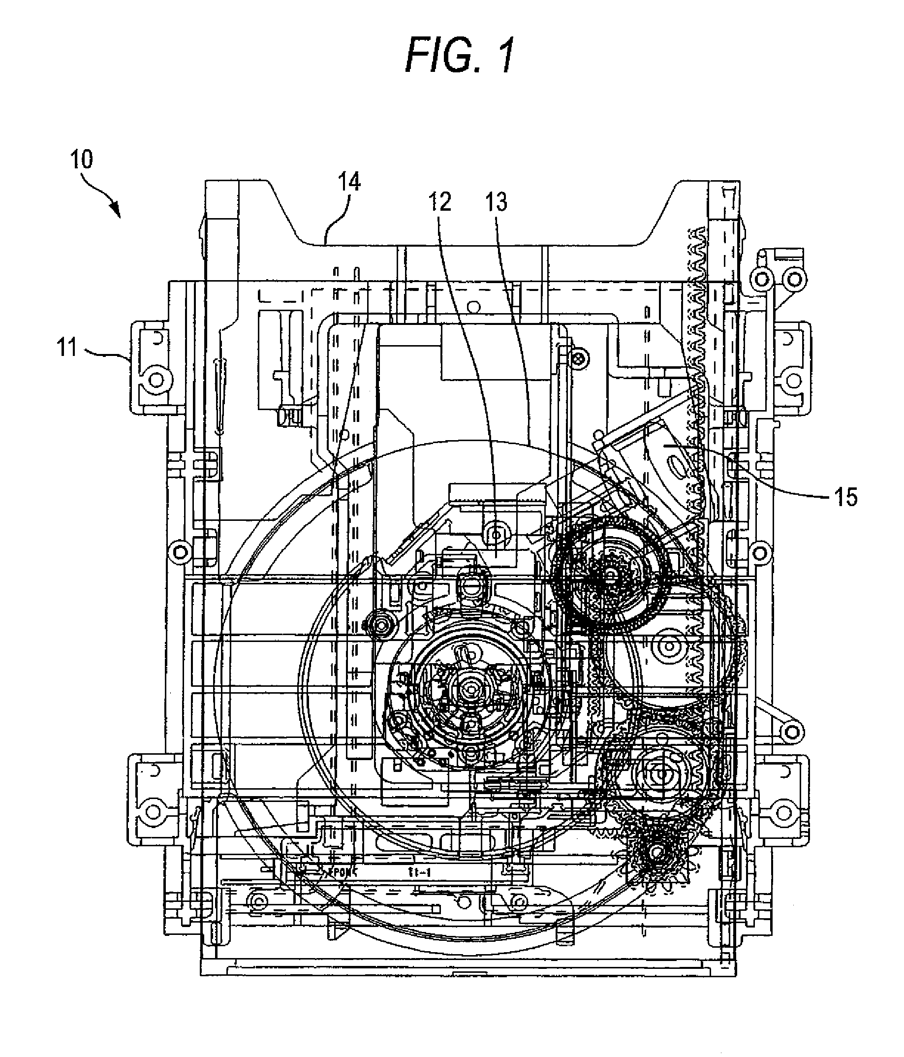
[0025]FIG. 1 is a plan view of a disk drive device. A disk drive device 10 includes a chassis 11 on which respective components are secured; a guide shaft 11a (see FIG. 2) secured to the chassis 11; an optical pickup 12 which moves along the guide shaft; a tray 14 for transferring the optical disk 13; and a loading motor 15 for driving the tray 14.

[0026]In this disk drive device 10, the optical pickup 12 is engaged to the guide shaft so that it is rotatable around the guide shaft and also is movable along the guide shaft.

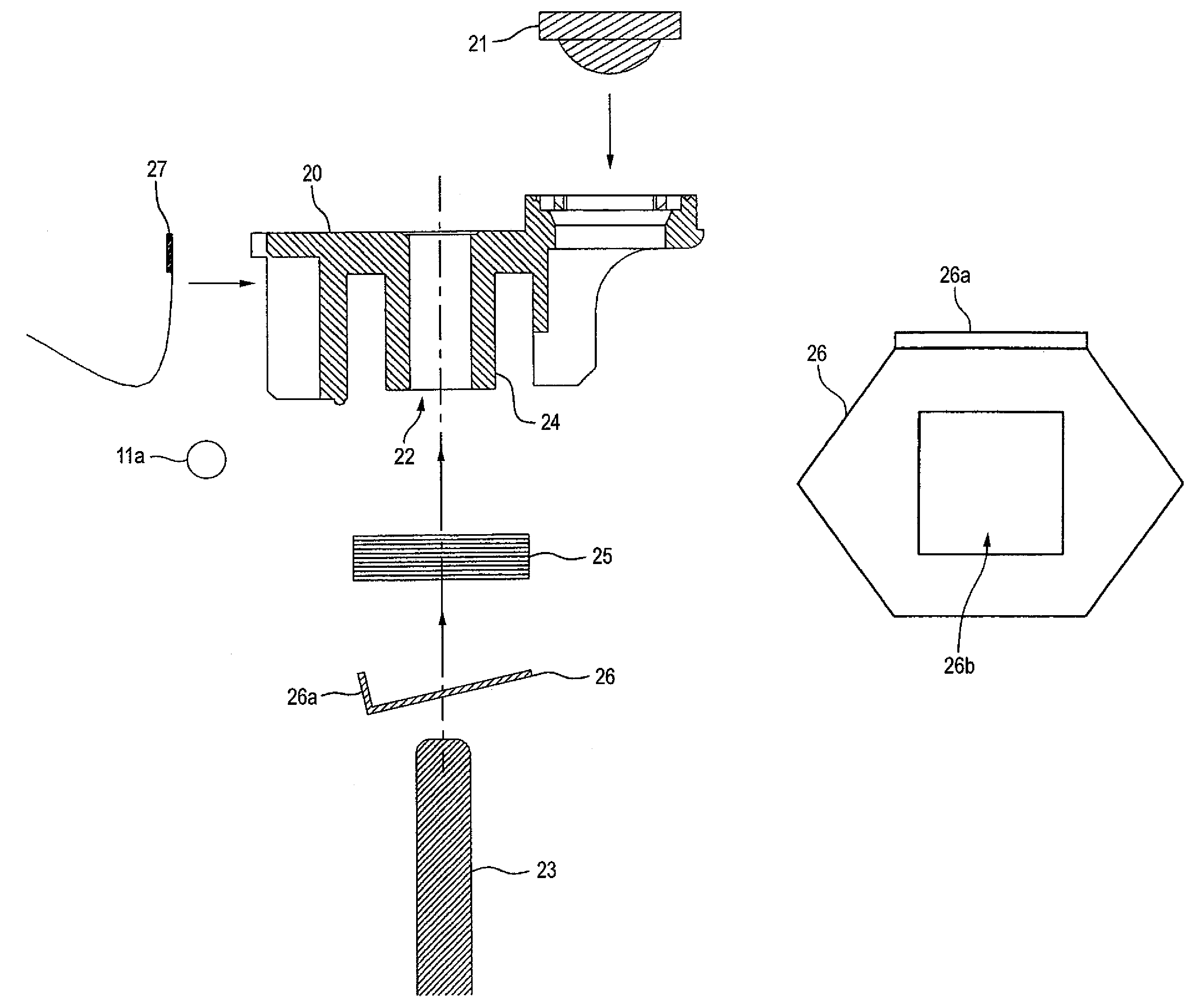
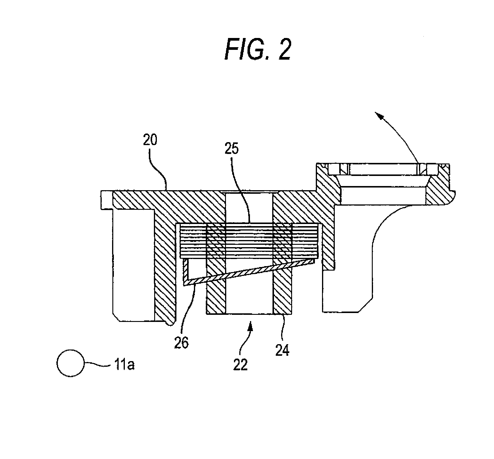
[0027]FIG. 2 is a sectional view of the optical pickup 1. FIG. 3 is an exploded view of FIG. 2. The optical pickup 1 includes a lens holder 20 and a lens holder supporting portion (not shown) for supporting the lens holder 20. The lens holder 20 holds an objective lens 21 for emitting a light beam to be projected onto the optical disk. The lens holder 20 has a sliding hole 22 made in the direction in parallel to a light beam emitting direction. The lens holder suppo...


PUM


Abstract

An optical disk apparatus that includes: a disk drive device having a guide shaft secured to a chassis and an optical pickup which is rotatably attached to the guide shaft and moves along the guide shaft. The optical pickup comprises a lens holder holding an objective lens for emitting a light beam to be projected onto an optical disk and having a sliding hole, a shaft passing through the sliding hole, a focus coil wound around an outer wall of the sliding hole, and a hexagonal magnetic plate fit over the outer wall of the sliding hole so as to be adjacent to the focus coil. One side of the hexagonal magnetic plate is bent toward the focus coil so that the magnetic plate is inclined with respect to a plane having a normal line parallel to a sliding direction of the lens holder.

Description

BACKGROUND OF THE INVENTION[0001]1. Field of the Invention[0002]This invention relates to an optical disk apparatus for reproducing and audio / video recording an optical disk such as CD and DVD and a disk drive device incorporated in the apparatus.[0003]2. Description of the Related Art[0004]An optical disk apparatus for reproducing or audio / video recording an optical disk such as CD and DVD incorporates a disk drive device for rotating the optical disk to be read. The disk drive device focuses optical beams on an optical disk surface using an objective lens and creates spots. The smaller size of the spots can realize the higher recoding density of information for the optical disk. The disk drive device, therefore, has a mechanism for reducing the spot size. Namely, the mechanism is prepared which causes the beams from the optical pickup to impinge on the optical disk surface at right angles to prevent coma aberration from being generated.[0005]On the optical disk, tracks with inform...

Claims


Application Information

Patent Timeline
Patent Type & Authority Patents(United States)
IPC IPC(8): G02B7/02
CPCG02B7/023G11B7/0933G11B7/0935G11B7/08582
Inventor HAMATANI, YUTARO
Owner FUNAI ELECTRIC CO LTD
Why Eureka
Try Eureka