
Pickup drive controller for optical disc drive

Inactive Publication Date: 2005-09-20
PANASONIC CORP
View PDF9 Cites 2 Cited by
  • Summary
  • Abstract
  • Description
  • Claims
  • Application Information

AI Technical Summary

Benefits of technology

[0016]Accordingly, as described above, when a lens offset before a seek is small or when a lens offset is seldom generated at a seek, a seek position is made close to a target position, whereby an optimum seek position at which the lens offset is canceled to the target position can be set with no waste. Therefore, access time at read is improved, and reliability of read is improved.
[0040]Therefore, read is performed actively when it can be performed, whereby unnecessary kickback is dispensed with to improve access time.

Problems solved by technology

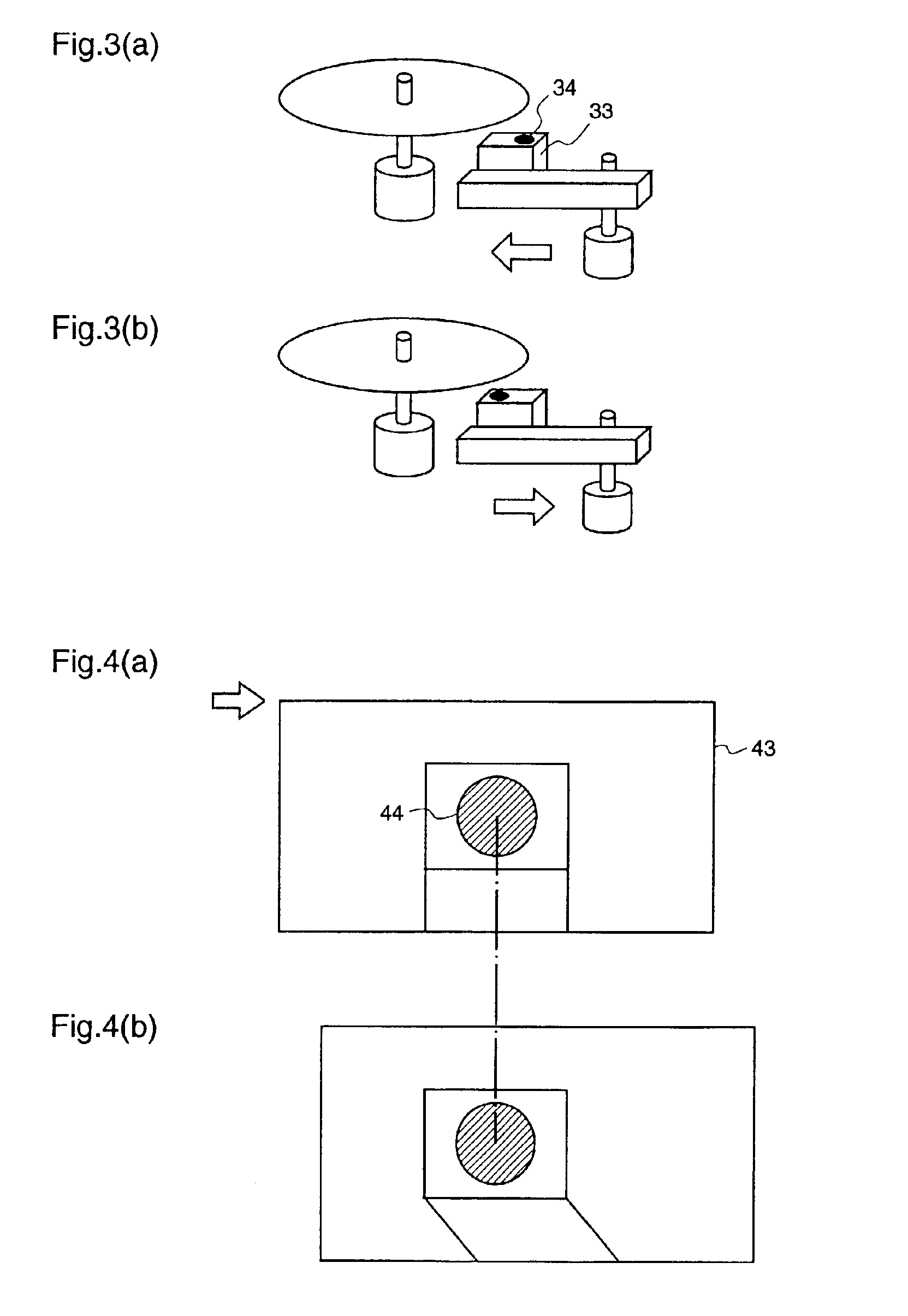
Another problem is that the feed inertially continues moving even after the feed seek is ended, resulting in an offset of the lens.
This results in the same problem as the above-described offset of the lens due to too fierce acceleration or deceleration of the feed movement.
Therefore, accurate data reading is disturbed, and further, the tracking servo becomes unstable when the lens is shifted because the tracking servo generates a positional signal from the reflected light of the disk.
Further, even when the seek position is set as described above, if the amount of generated lens offset is extremely large, the lens offset is not removed by the time of read start, and a read error may occur.

Method used


Image

  • Pickup drive controller for optical disc drive
  • Pickup drive controller for optical disc drive
  • Pickup drive controller for optical disc drive

Examples


embodiment 1

(Embodiment 1)

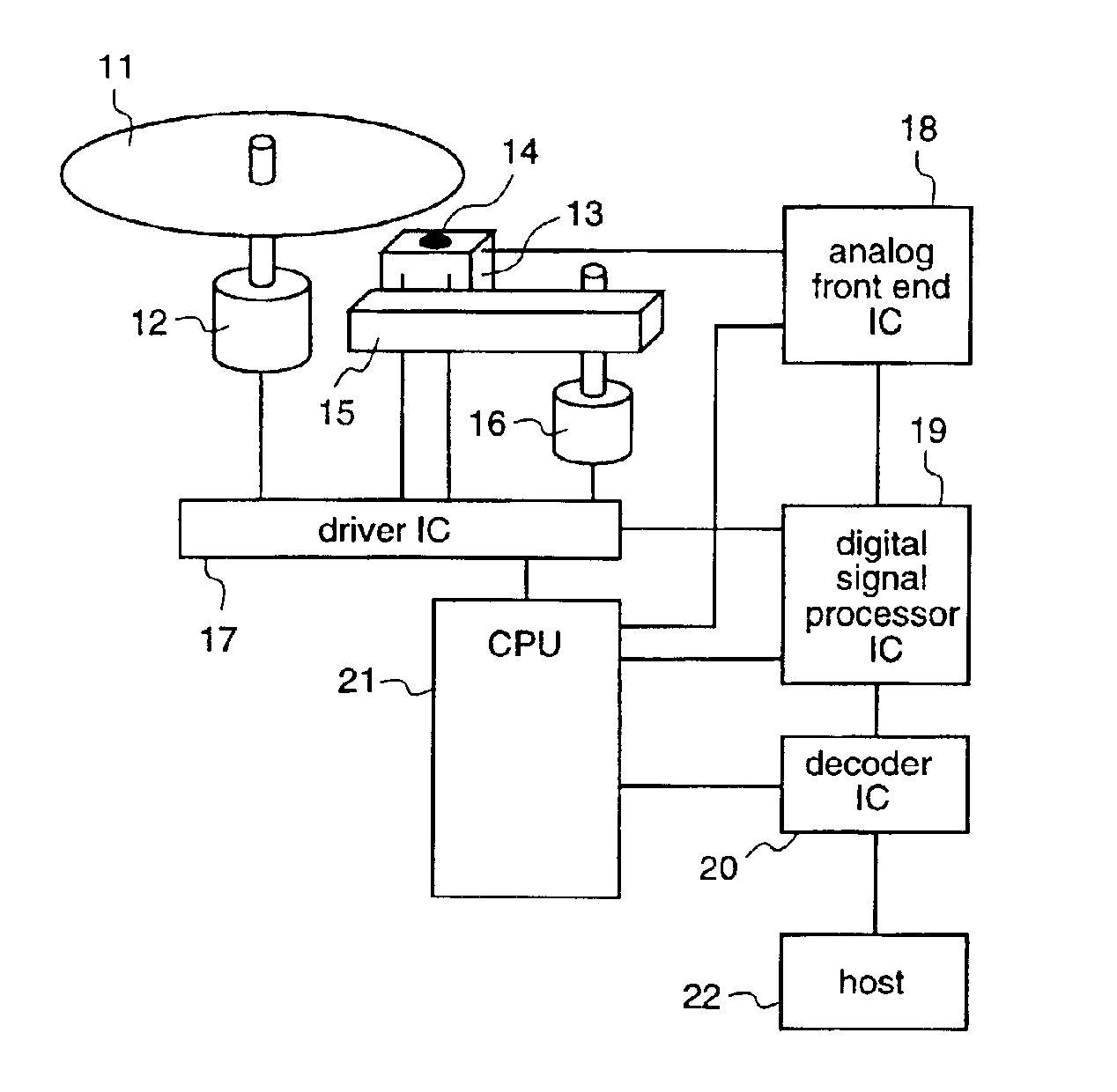
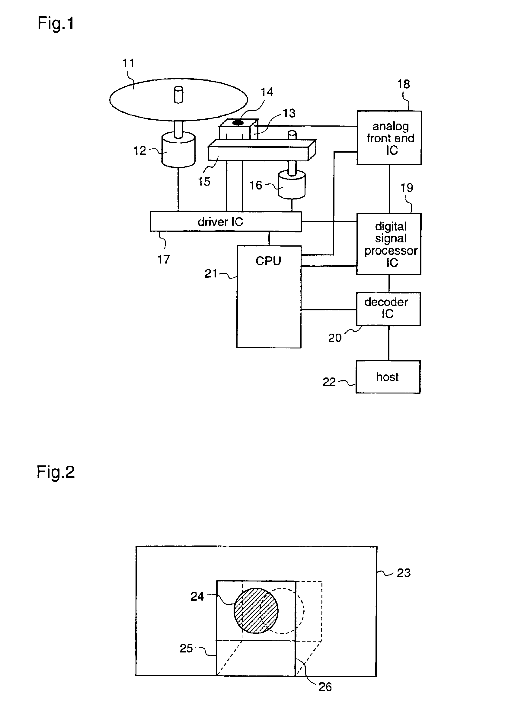
[0060]A first embodiment which corresponds to an optical disk drive as defined in the first through third aspects of the present invention will be described with reference to FIGS. 1 and 8 to 13.

[0061]In this first embodiment, when a lens shift before a seek is insignificant and a seek is carried out in units of several seeks that hardly cause lens shift, the number of seeks is set at minimum. At other times, the number of seeks is determined on the basis of the amount of lens shift before a seek and the number of seeks. Thereby, generation of unnecessary seeks is avoided to improve access time.

[0062]In a block diagram of FIG. 1, the amount of offset of a lens 14 is inputted to an A / D converter terminal of a CPU 21 of the optical disk drive from a pickup 13 through an analog front end IC 18. Therefore, the CPU 21 performs A / D conversion of an output signal from a photoreceptor unit of the pickup 13 by a built-in A / D converter and detects an offset, thereby obtaining th...

embodiment 2

(Embodiment 2)

[0095]Next, a second embodiment which corresponds to an optical disk drive as defined in the fourth through sixth aspects of the present invention will be described with reference to FIGS. 1 and 14. The same constituents as those described in the first embodiment will be denoted by the same reference numerals, and description therefor will be omitted.

[0096]In this second embodiment, a feed position is calculated on the basis of a seek position when the previous seek is ended and a seek position when the next seek is started, and a further seek position is set before a read start position when the feed is moved by a prescribed value or more, thereby canceling an offset of the feed due to the continuous movement of the feed to enhance reading performance.

[0097]In order to make the second embodiment correspond to the invention according to the fourth aspect, when a seek is to be performed first according to a read instruction from the host 22 shown in FIG. 1, the CPU 21 c...

embodiment 3

(Embodiment 3)

[0117]A third embodiment which corresponds to an optical disk drive as defined in the seventh through ninth aspects of the present invention will be described with reference to FIGS. 1, 15, 16, 17 and 18.

[0118]In this third embodiment, a seek position is set just before a read start position, and the processing shifts to a read when a lens shift after the seek is at a level having no problem. When a lens shift occurs, a kickback of one track is performed and continued until the lens shift is settled. Therefore, the access time is improved because the processing promptly shifts to the read when no lens shift occurs. On the other hand, when a lens shift occurs, this is suppressed by kickback to improve reading performance.

[0119]In the block diagram of FIG. 1, the amount of offset of the lens 14 is inputted to the A / D converter terminal of the CPU 21 from the pickup 13 via the analog front end IC 18. Therefore, the CPU 21 subjects an output signal from the photoreceptor u...


PUM


Abstract

In an optical disk drive, in order to cancel a lens offset which may occur when performing a seek followed by a read, a seek position must be set several sectors before a target position for the read, resulting in a delay in access time. A lens offset amount is measured when a seek followed by read is started, and how many sectors before a read target position a seek position must be set is determined on the basis of two parameters, namely, the lens offset amount and a number of seek tracks. Thereby, an optimum seek position at which the lens offset is canceled can be set with no waste, resulting in an improvement in access time.

Description

TECHNICAL FIELD[0001]The present invention relates to a controller for driving a pickup of an optical disk drive as typified by a CD-ROM drive and, more particularly, to a pickup drive controller which performs a seek (fast-forward / fast-rewind) followed by a read, with no waste, to improve the stability of the read.BACKGROUND ART[0002]In recent years, optical disk drives have rapidly became standard-equipment on personal computers, and they have become an indispensable feature of personal computers along with hard disk drives. While CD-ROM drives have initially made up the majority of optical disk drives, DVD-ROM drives having a larger capacity than that of CD-ROM drives or recordable or rewritable CD-R / CD-RW drives which are standard-equipment on personal computers these days, and further, DVD-R or DVD-RAM drives have appeared on the market. Thus, there are no bounds to enhancement in performance and function of optical disk drives.[0003]An example of an optical disk drive is illus...

Claims


Application Information

Patent Timeline
IPC IPC(8): G11B7/085C12Q1/58G01N33/62
CPCG11B7/08505G11B7/08517C12Q1/58G01N33/62G01N2333/205G01N33/56911G01N33/58
Inventor KAJI, TOSHIHIKO
Owner PANASONIC CORP
Learn More