Bar Code Reading Apparatus and Bar Code Reading Method

Inactive Publication Date: 2009-11-05
KEYENCE
View PDF3 Cites 4 Cited by
  • Summary
  • Abstract
  • Description
  • Claims
  • Application Information

AI Technical Summary

Benefits of technology

[0018]In the first and fourth aspects of the present invention, a bar code reading apparatus includes: a light-emitting element that emits light; a mirror mechanism that changes an emission direction of the light emitted from the light-emitting element so that the light can cyclically scan a bar code at a plurality of different locations, with certain regularity; and a light-receiving element that receives reflected light from the bar code. Bar code information is obtained based on a received-light signal obtained by photoelectrically converting reflected light for each scanning line received by the light-receiving element. Reading result information about whether bar code information has been able to be read normally in a scanning cycle unit is stored in association with the plurality of locations and information on a condition set upon reading. Based on stored reading result information which is obtained in an immediately previous scanning cycle, it is determined whether bar code information in an identical relative location in the immediately previous scanning cycle has been able to be read normally. If bar code information has been able to be read normally, then information on a condition set upon reading in the immediately previous scanning cycle is maintained. If bar code information has not been able to be read normally, then information on a condition set upon reading in the immediately previous scanning cycle is changed. By cyclically scanning a bar code at a plurality of different locations, with certain regularity, when bar code information has been able to be read normally in an immediately previous scanning cycle, bar code information is read using a condition set upon reading as it is, and when bar code information has not been able to be read normally in an immediately previous scanning cycle, a condition set upon reading can be changed to a different condition. Thus, the condition can promptly converge to an appropriate condition for reading bar code information. Accordingly, for example, even when a bar code is affixed to a cylindrical to-be-detected object or when only some of scanning lines hit a bar code area, information on an appropriate condition can be promptly identified, enabling to stably read bar code information.
[0019]In the second and fifth aspects of the present invention, the information on a condition includes a gain value set by an amplifier circuit that amplifies the received-light signal, and in a first scanning cycle after a start of scanning, a new gain value is calculated based on an immediately previously stored gain value and amount of received light which are obtained when scanning is performed at another location. In a subsequent scanning cycle, when bar code information has been able to be read normally, a gain value in an identical relative location in an immediately previous scanning cycle is read, and when bar code information has not been able to be read normally, a new gain value is calculated based on an immediately previously stored gain value and amount of received light which are obtained when scanning is performed at another location. By this, a new gain value can be calculated only for a location at which bar code information has not been able to be read normally in an immediately previous scanning cycle, based on a stored gain value and an amount of received light obtained when scanning is performed at an immediately previous location; accordingly, a gain value can be promptly stabilized.
[0020]In the third and sixth aspects of the present invention, the information on a condition includes a gain value set by an amplifier circuit that amplifies the received-light signal, and a predetermined number of gain values to be set are stored. When bar code information has been able to be read normally, a same gain value as that used to read the bar code information is read in scanning at a next location, and when bar code information has not been able to be read normally, a gain value is set by cyclically changing the stored gain values. By this, every time bar code information has not been able to be read normally, a gain value does not need to be calculated and by repeatedly performing scanning until an appropriate gain value is obtained, a gain value can be promptly stabilized.
[0021]According to the above-described configuration, by cyclically scanning a bar code at a plurality of different locations, with certain regularity, when bar code information has been able to be read normally in an immediately previous scanning cycle, bar code information is read using a condition set upon reading, as it is, and when bar code information has not been able to be read normally in an immediately previous scanning cycle, a condition set upon reading can be changed to a different condition. Thus, the condition can promptly converge to an appropriate condition for reading bar code information. Accordingly, for example, even when a bar code is affixed to a cylindrical to-be-detected object or when only some of scanning lines hit a bar code area, information on an appropriate condition can be promptly identified, enabling to stably read bar code information.

Problems solved by technology

Hence, when gain values are uniformly increased or decreased as in the conventional cases, even though an appropriate amount of received light can be ensured for a certain scanning line, the amount of received light may be too large or too small for other scanning lines, causing a problem that a bar code may not be able to be read normally.
It may be considered to obtain a gain value as an average value, based on past amounts of received light of reflected light; however, once a too large or too small amount of received light is stored, it requires a considerable amount of time for a gain value to converge.
Therefore, there is a problem that it takes time for bar code reading to be stabilized after a start of bar code reading.

Method used


Image

  • Bar Code Reading Apparatus and Bar Code Reading Method
  • Bar Code Reading Apparatus and Bar Code Reading Method
  • Bar Code Reading Apparatus and Bar Code Reading Method

Examples


first embodiment

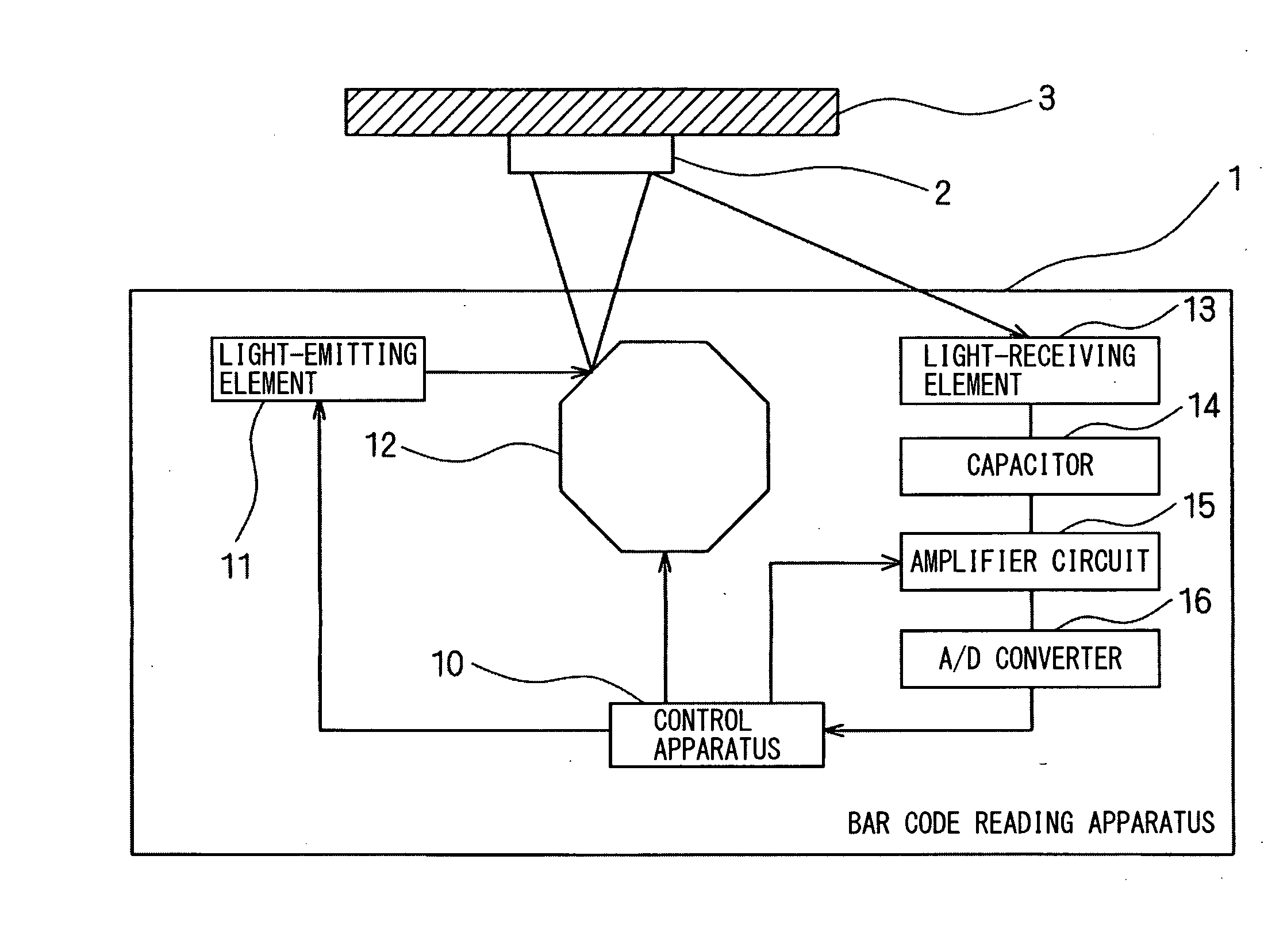
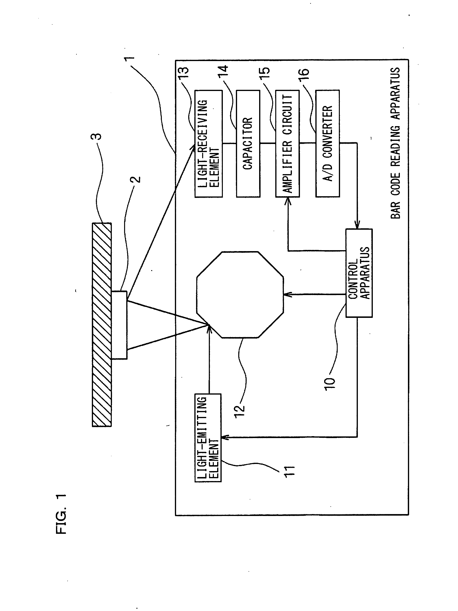
[0037]FIG. 1 is a block diagram schematically showing a configuration of a bar code reading apparatus according to a first embodiment of the present invention. As shown in FIG. 1, in a bar code reading apparatus 1 according to the first embodiment, light is emitted from a light-emitting element 11, such as semiconductor laser or an LED, and the light is reflected off a surface of a polygon mirror 12 which is a mirror mechanism, toward a to-be-detected object 3.

[0038]The reflected light that is reflected off the polygon mirror 12 is guided to a bar code 2 affixed to the to-be-detected object 3. A light-receiving element 13, such as a CCD or a photodiode, receives reflected light from the bar code 2 and outputs a received-light signal obtained by photoelectrically converting the received reflected light. A direct-current component of the received-light signal is eliminated by a capacitor 14, the resulting received-light signal is amplified according to a gain value set by an amplifier...

second embodiment

[0094]A configuration of a bar code reading apparatus according to a second embodiment of the present invention is the same as that of the first embodiment and thus the same reference numerals are provided and a detailed description thereof is not given. Although the second embodiment is the same as conventional cases in performing a reading process at each scanning line, the second embodiment is different from the first embodiment in that a determination as to whether reading has been able to be performed normally is made for each scanning line and if reading has not been able to be performed normally, then a plurality of gain values stored in advance are repeatedly set in a predetermined order.

[0095]FIG. 11 is a flowchart showing steps of a gain value modification process performed by a CPU 20 of a control apparatus 10 of a bar code reading apparatus 1 according to the second embodiment of the present invention. In FIG. 11, the CPU 20 of the control apparatus 10 sets a counter n t...


PUM


Abstract

Reading result information about whether bar code information has been able to be read normally in a scanning cycle unit is stored in association with a plurality of locations and information on a condition set upon reading. When it is determined, based on stored reading result information which is obtained in an immediately previous scanning cycle, that bar code information in an identical relative location in the immediately previous scanning cycle has been able to be read normally, information on a condition set upon reading in the immediately previous scanning cycle is read. When it is determined that bar code information has not been able to be read normally, information on a condition that differs from information on a condition set upon reading in the immediately previous scanning cycle is set.

Description

CROSS-REFERENCE TO RELATED APPLICATIONS[0001]The present application claims foreign priority based on Japanese Patent Application No. 2008-118712, filed Apr. 30, 2008, the contents of which is incorporated herein by reference.BACKGROUND OF THE INVENTION[0002]1. Field of the Invention[0003]The present invention relates to a raster scan type bar code reading apparatus and a bar code reading method. More particularly, the present invention relates to a raster scan type bar code reading apparatus and a bar code reading method that are capable of making optimal gain adjustment based on a reading result.[0004]2. Description of the Related Art[0005]Conventionally, numbers of bar code readers have been developed that use semiconductor laser as a light-emitting element and scan a bar code by a light beam. To ensure scanning of a bar code, a light-receiving element needs to receive reflected light of a light beam emitted from a light-emitting element, at an appropriate intensity of received l...

Claims


Application Information

Patent Timeline
IPC IPC(8): G06K7/10
CPCG06K7/10544
Inventor MATSUDA, HAJIME
Owner KEYENCE
Why Eureka
Try Eureka