Digital television broadcast signal receiver

a digital television and receiver technology, applied in the field of digital television (tv) broadcast signal receivers, can solve the problems of time and energy waste, old channel receivable, sudden bankruptness of tv stations,

Inactive Publication Date: 2008-12-02
FUNAI ELECTRIC CO LTD
View PDF8 Cites 0 Cited by
  • Summary
  • Abstract
  • Description
  • Claims
  • Application Information

AI Technical Summary

Benefits of technology

[0009]A purpose of the present invention is to provide a digital TV broadcast signal receiver, by which a term necessary for deciding an optimum signal receiving direction of each channel can be shortened, and a number of times for switching effective signal receiving direction can be reduced without performing scanning operation to indistinctive signal receiving directions in practice, when a simplified multi-directional antenna is connected thereto.
[0014]By such a configuration, when the multi-directional antenna having a second number of the signal receiving directions smaller than the first number of signal receiving directions is connected to the tuner of the digital TV broadcast signal receiver, even though the digital TV broadcast signal receiver can switch the effective signal receiving direction of the antenna to all of the first number of the signal receiving directions, only one signal receiving direction among adjoining signal receiving directions more than two showing substantially the same signal receiving conditions is made effective so as to receive the TV broadcast signal. Consequently, it is possible to shorten a term necessary for deciding an optimum signal receiving direction of each channel, and to reduce a number of times for scanning signal receiving directions without performing scanning operation to indistinctive signal receiving directions in practice, when a simplified multi-directional antenna is connected the digital TV broadcast signal receiver in compliance with the technical standard. The number of the signal receiving directions of the multi-directional antenna is not limited to an even number.
[0017]Still furthermore, it is possible that the controller can perform an automatic scanning operation for switching the effective signal receiving direction of the multi-directional antenna to a signal receiving direction, in which the signal receiving condition of an optional channel is highest.

Problems solved by technology

In contrast, a TV station suddenly becomes bankrupt.
Therefore, it happens that a new channel, which cannot be received beforetime, can be received, or an old channel receivable long before cannot be received.
Consequently, time and energy are wasted for deciding the optimum signal receiving direction of each channel.

Method used


Image

  • Digital television broadcast signal receiver
  • Digital television broadcast signal receiver
  • Digital television broadcast signal receiver

Examples


Embodiment Construction

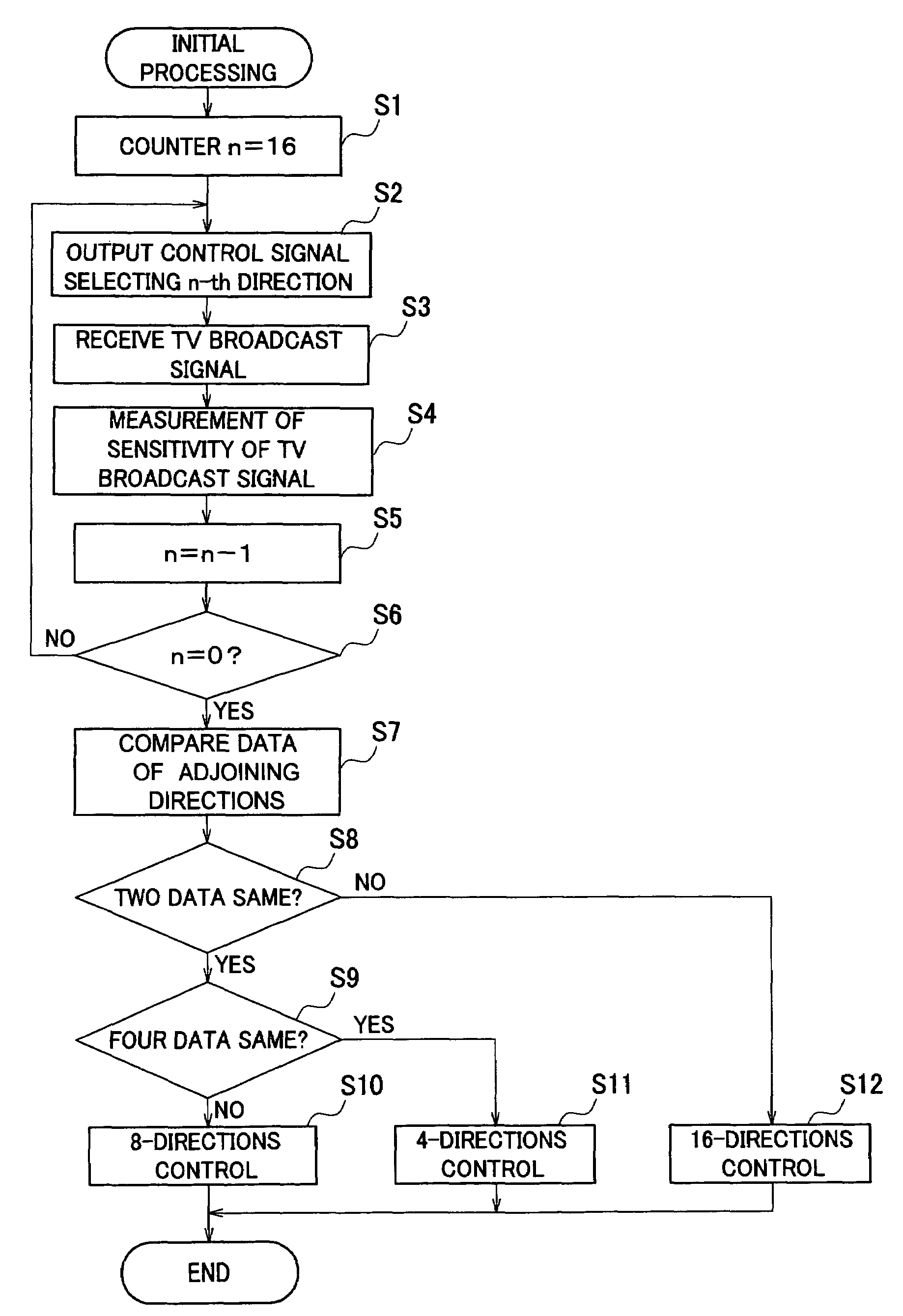
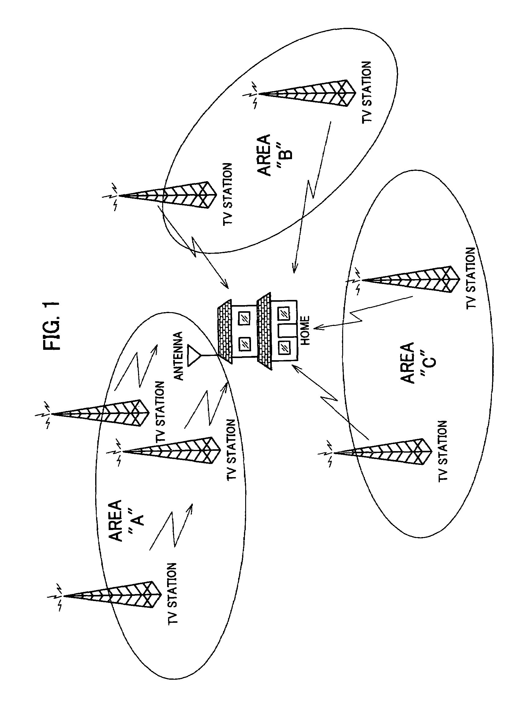
[0023]A digital TV broadcast signal receiver in accordance with an embodiment of the present invention is described with reference to figures. A circumstance for receiving TV broadcast signals in home is shown in FIG. 1. In an area where grand-based digital TV broadcast is performed, when a sensitivity of received signal of a TV broadcast signal is equal to or larger than a predetermined threshold value, an image having a predetermined image quality can be obtained by correction. Thus, it is possible to view TV programs by receiving TV broadcast signals which are delivered from TV stations existing at many positions in such as areas designated by symbols A, B, C, and so on, as shown inFIG. 1. According to such a circumstance, various types of multi-directional antennas called smart antenna having a plurality of signal receiving directions are put into practical use.

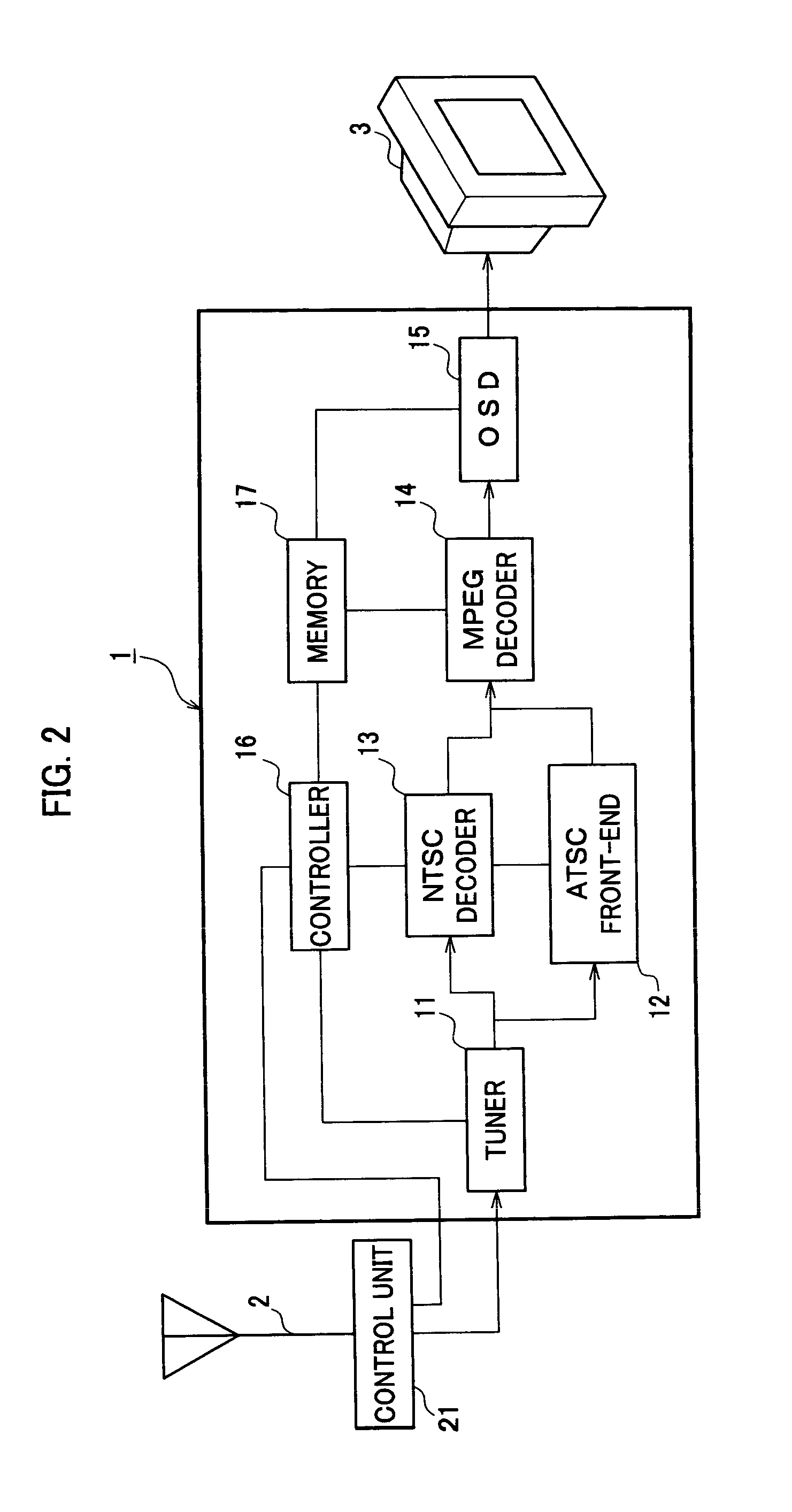
[0024]The digital TV broadcast signal receiver 1 can receive analogue TV broadcast signals, and it performs a control o...


PUM


Abstract

In a digital TV broadcast signal receiver connected to a multi-directional antenna called smart antenna, having a first number, for example, sixteen of signal receiving directions defined in a technical standard such as EIA-909, a simplified multi-directional antenna having a second number, for example, four or eight signal receiving directions smaller than the first number is connectable. When a multi-directional antenna is connected, an initial processing is performed for confirming a number of signal receiving directions of the multi-directional antenna. When the multi-directional antenna is simplified one, the digital TV broadcast signal receiver treats the signal receiving directions more than two showing substantially the same signal sensing conditions as the same direction. Therefore, a number of times for switching the effective signal receiving direction of the multi-directional antenna can be reduced without switching indistinctive signal receiving directions in practice.

Description

BACKGROUND OF THE INVENTION[0001]1. Field of the Invention[0002]The present invention relates to a digital television (TV) broadcast signal receiver that can receive digital television broadcast signals such as ATSC (Advanced television systems Committee).[0003]2. Description of the Related Art[0004]In the North American Continent where an ATSC digital television broadcast (it is abbreviated to a hereinafter TV broadcast) is performed, plains are dotted with metropolises, so that various TV broadcast signals broadcasted in the suburbs of each metropolis can be received at other cities or the halfway point of the cities. In consideration from a user who receives the TV broadcast signals, since many TV broadcast signals are transmitted in various directions, it is necessary to regulate a direction of an antenna in an orientation to a TV broadcasting station from which a program which he wants to watch is delivered. Therefore, a multi-directional antenna such as a smart antenna is put ...

Claims


Application Information

Patent Timeline
Patent Type & Authority Patents(United States)
IPC IPC(8): H04N7/20H04N5/46H04N5/50H04B1/16H04B7/08H04B7/10H04N5/44H04N9/65
CPCH04N5/4401H04N21/44209H04N21/4384H04N21/4263H04B7/0808H04N21/42638H04N21/426
Inventor TAKAGI, TOSHIHIROKAWAI, MASANORIYAMAMOTO, NAOKI
Owner FUNAI ELECTRIC CO LTD
Why Eureka
Try Eureka