
Supply module having a heating device for conveying an operating/auxiliary agent capable of freezing

a technology of heating device and auxiliary agent, which is applied in the direction of mechanical/engine, ohmic-resistance waterproof/air-tight seal, lighting and heating apparatus, etc., can solve the problems of deterioration in the thawing behavior, comparatively high filter construction, and excessive localized dissipation of energy which cannot be dissipated to the environmen

Active Publication Date: 2022-07-05
ROBERT BOSCH GMBH
View PDF16 Cites 0 Cited by
  • Summary
  • Abstract
  • Description
  • Claims
  • Application Information

AI Technical Summary

Benefits of technology

[0017]The solution proposed according to the invention is distinguished in that both the main heater as well as the auxiliary heater of the supply module are embodied having a uniformly configured plug interface for both heaters. The electrical contacts that lie in the region of the pot wall permit the omission of elastomeric seals on account of which the ruggedness of the supply module proposed according to the invention is significantly increased. A significant reduction in terms of components can be achieved by virtue of the simplified sealing and fastening concept implemented without small parts such as, for example, O-rings from elastomer. There is the possibility for flexible assembly concepts for the main heater and for the auxiliary heater to be implemented on the uniformly configured plug interface of the electrical contacts, such that the main heater and the auxiliary heater, respectively, can be assembled by external suppliers, or else an assembly can take place at the manufacturer of the supply module. This assembly by virtue of the reduced assembly steps is significantly simplified, on account of which a reduction in costs can be achieved.
[0019]In the case of the heater concept proposed according to the invention that comprises the main heater and the auxiliary heater, in terms of the main heater a pot-shaped heater which moreover has a reservoir effect can be implemented, since a reserve of the freezing-capable reduction agent can be heated in the inboard cavity of the heater pot and, accordingly, can be maintained in a liquid state at low external temperatures. The use of a pressed screen configured in a meandering shape, in the interaction with the heat-conducting insert-molding by way of the plastics material, enables a compensation of the thermal expansion. An integrated standard interface, in particular for electrically contacting the auxiliary heater, can be represented by the solution proposed according to the invention.
[0020]In terms of the auxiliary heater, a standardized interface for electrically contacting and fastening auxiliary heaters, whether proprietary heaters or third-party heaters, in a simple manner is achieved by the solution proposed according to the invention. The solution proposed according to the invention enables a flexible manufacturing concept to be implemented, whereby open pin ends in the case of an auxiliary heater not being required on the supply module can be closed in a liquid-tight manner by way of a cover cap. The configuration of the seal as a materially integral connection is performed, for example, by hot-tool welding. A significant increase in ruggedness can be achieved in that small parts and soft-material seals can be omitted in the case of the heater concept proposed according to the invention, and that heating strategies in which a total heating output can be flexibly split between the main heater and the optionally provided auxiliary heater can be implemented in terms of control by way of a common controller. This is performed so as to depend on the respective state of the overall system.

Problems solved by technology

On account thereof, and caused by the installation space that is available only to a limited extent, a comparatively high filter construction results.
The cause thereof is an excessive localized dissipation of energy which cannot be dissipated to the environment.
However, the reduction of the heater output that is associated therewith leads to a deterioration in the thawing behavior.
Moreover, the additional parts installed, for example annular seals, elastomeric components, and further small parts, represent potential weak spots, reduction agent potentially making its way to critical functional group locations in the case of a failure of said parts in operation.

Method used


Image

  • Supply module having a heating device for conveying an operating/auxiliary agent capable of freezing
  • Supply module having a heating device for conveying an operating/auxiliary agent capable of freezing
  • Supply module having a heating device for conveying an operating/auxiliary agent capable of freezing

Examples


Embodiment Construction

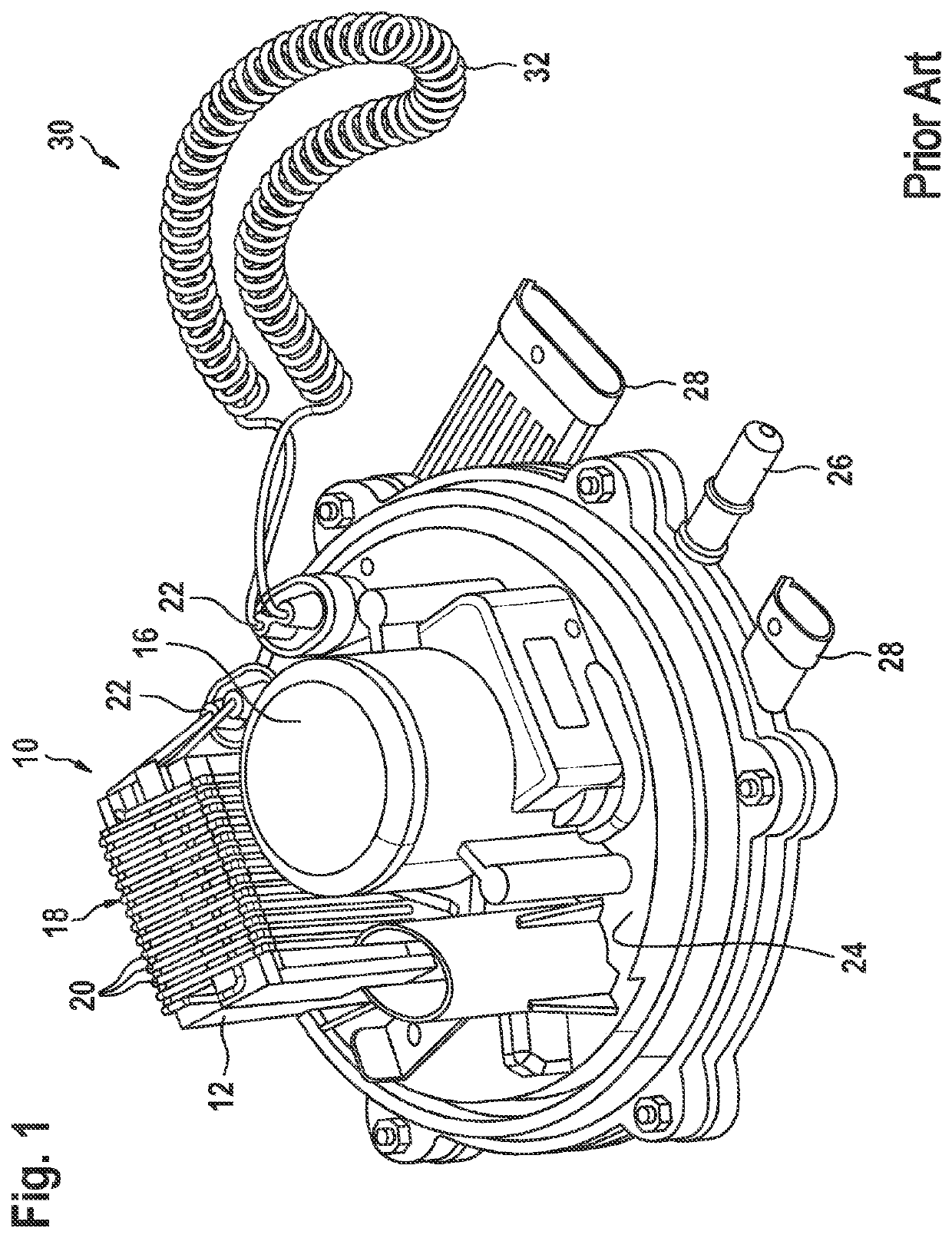
[0029]FIG. 1 shows a supply module according to the prior art.

[0030]A supply module 10 comprises a filter 12 and a conveying apparatus 16. The filter 12 is surrounded by a main heater 18 which in the exemplary embodiment according to FIG. 1 comprises a plurality of heater-wire coils 20. Electrical connectors 22 for electrically contacting the main heater 18 as well as an auxiliary heater 30 are located on the upper side of the supply module 10. The supply module 10 according to the illustration in FIG. 1 furthermore comprises a support member 24 on which both a hydraulic connector 26 for the operating / auxiliary agent, in particular a freezing-capable reduction agent, as well as connector plugs 28 for electrically contacting the support member 24 of the supply module 10 are configured.

[0031]The auxiliary heater 30 which in the exemplary embodiment according to FIG. 1 is configured as a helically wound heater wire 32 is connected to one of the electrical connectors 22.

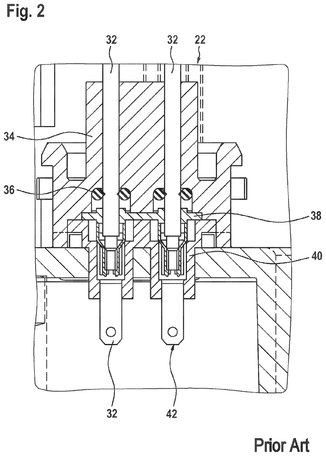
[0032]FIG. 2 sho...


PUM


Abstract

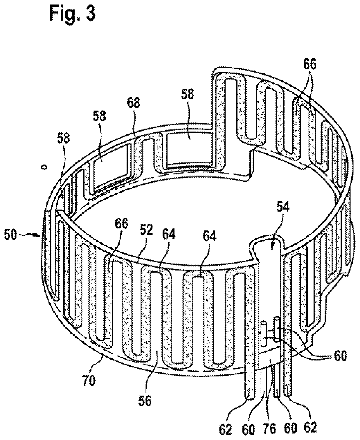
The invention relates to a supply module (10) for conveying an operating / auxiliary agent capable of freezing for the exhaust gas aftertreatment of an internal combustion engine and for heating a reservoir holding the operating / auxiliary agent capable of freezing. The supply module (10) comprises a main heater (18) and an auxiliary heater (30), which are electrically contacted on a supporting body (24). A pot wall (52) of a heating pot (50) comprises electrical contacts (62) of the main heater (18) and electrical contacts (60) of the auxiliary heater (30).

Description

BACKGROUND OF THE INVENTION[0001]The present invention relates to a device for heating an operating / auxiliary agent for an internal combustion engine, wherein the operating / auxiliary agent is in particular a freezing-capable reduction agent for reducing pollutants in the exhaust gas of the internal combustion engine.[0002]DE 10 2013 217 333 A1 relates to an in-tank filter and to a filter medium that is suitable therefor. The in-tank filter serves for filtering a liquid, and has a first filter side and a second filter side. A receptacle space is disposed between said two filter sides; furthermore, filtered liquid from the receptacle space is dischargeable by way of a connector. In order for a housing to be formed, an annular circumferential wall which encloses the first filter side and the second filter side is provided, wherein at least one filter side has a pleated filter medium.[0003]DE 10 2013 222 288 A1 refers to a supply module for conveying an operating / auxiliary agent. A supp...

Claims


Application Information

Patent Timeline
Patent Type & Authority Patents(United States)
IPC IPC(8): F24H1/00H05B3/04H05B3/44F01N3/20F01N3/28F24H1/20
CPCF24H1/009F01N3/206F01N3/2066F01N3/2896F24H1/202H05B3/04H05B3/44F01N2610/02F01N2610/10F01N2610/1406H05B2203/013H05B2203/014H05B2203/02Y02T10/12
Inventor DOEFFINGER, ANDREASKIONTKE, MARTIN
Owner ROBERT BOSCH GMBH
Learn More