Paper feeding apparatus

a technology of feeding apparatus and paper, which is applied in the direction of thin material processing, instruments, article separation, etc., to achieve the effects of reducing the development time of the apparatus, improving the operability of the apparatus, and facilitating cost reduction

Inactive Publication Date: 2011-05-10
SHARP KK
View PDF10 Cites 0 Cited by
  • Summary
  • Abstract
  • Description
  • Claims
  • Application Information

AI Technical Summary

Benefits of technology

[0017]An object of the present invention is to provide, as to paper feeding apparatuses respectively employing accessing schemes that are different from each other of an image forming apparatus, a paper feeding apparatus of an image forming apparatus, that has the configuration to enable the apparatus to be usable regardless of the accessing scheme thereof and that is adapted to facilitate cost reduction by reducing the term of development of the apparatus and improve the operability of the apparatus.
[0029]Another object of the present invention is to provide the paper feeding apparatus, wherein the supporting member is roller that can freely rotate forward, backward, rightward and leftward.

Problems solved by technology

Therefore, the above publication does not disclose any technical idea that rationalization is facilitated by standardizing the constituting members for the above apparatuses respectively employing accessing schemes that are different from each other.

Method used


Image

  • Paper feeding apparatus
  • Paper feeding apparatus
  • Paper feeding apparatus

Examples


Embodiment Construction

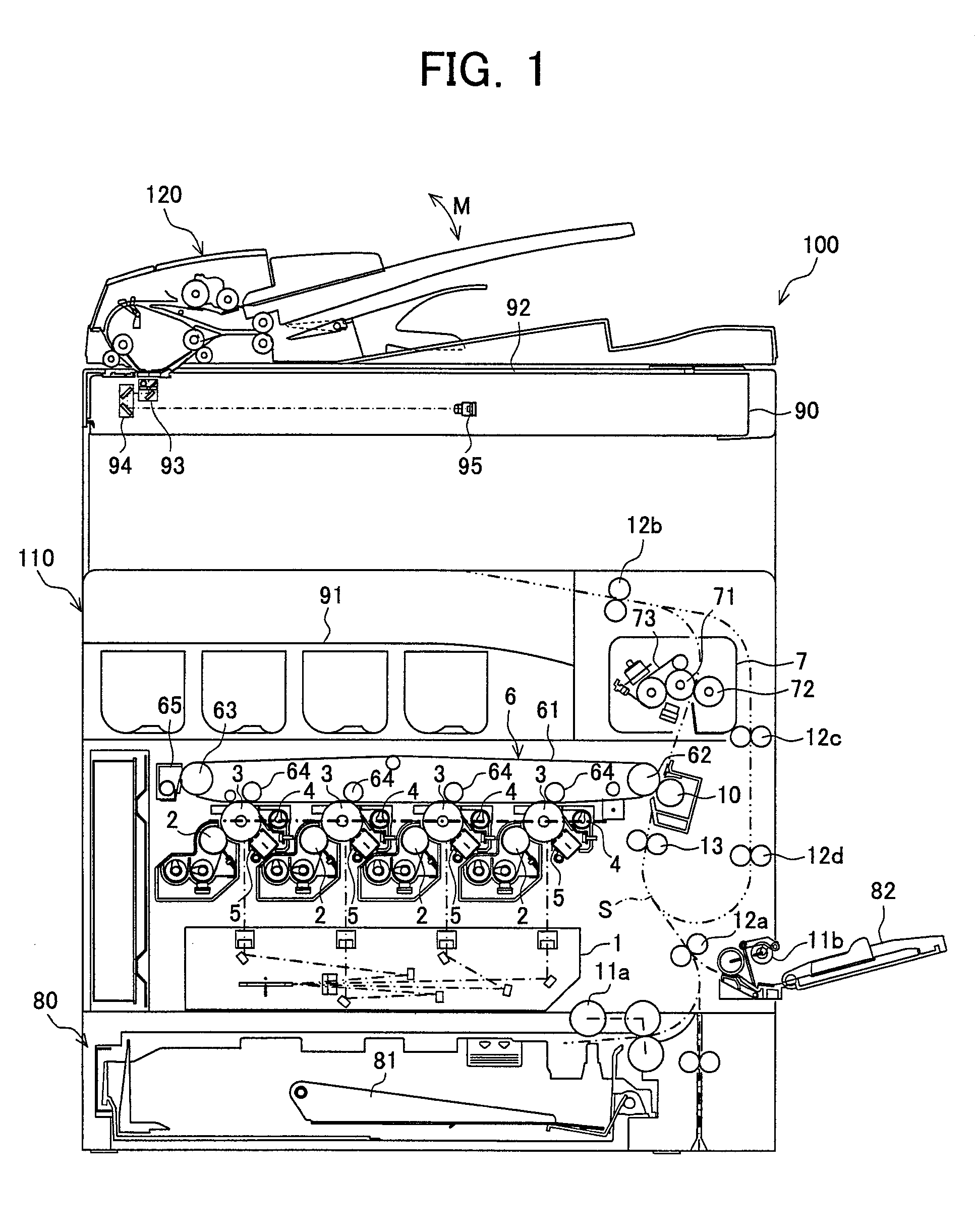
[0038]FIG. 1 is a diagram of an exemplary configuration of an MFP (multifunction peripheral) to which a paper feeding apparatus of the present invention is applied. An MFP 100 forms a color or monochrome image onto a predetermined sheet (recording paper sheet) according to image data transmitted externally. The MFP 100 is configured by an apparatus main body 110 and an automatic document processing apparatus 120. The apparatus main body 110 is configured by having an exposure unit 1, a developer 2, a photo-sensitive drum 3, a cleaner unit 4, an electric charger 5, an intermediate transferring belt unit 6, a fixing unit 7, a paper feeding cassette 81, a paper sheet receiving tray 91, etc.

[0039]On the top of the apparatus main body 110, a document loading base 92 consisting of a transparent glass plate on which a document is loaded is provided, and the automatic document processing apparatus 120 is attached above the document loading base 92. The automatic document processing apparatu...


PUM


Abstract

A paper feeding apparatus used in a state where the apparatus accumulates paper sheets for an image forming apparatus to form images thereon and the paper feeding apparatus is attached to a main body of the image forming apparatus, wherein an engaging-holding member is provided for an exterior wall face of the paper feeding apparatus, and the engaging-holding member engages and holds the paper feeding apparatus with an exterior housing of the image forming apparatus so as to enable the paper feeding apparatus to move into / from the exterior housing of the image forming apparatus, is provided for an exterior wall face of the paper feeding apparatus, and wherein the engaging-holding member is provided for a specific one of the exterior wall faces of the paper feeding apparatus corresponding to the moving direction determined according to the specification of the image forming apparatus.

Description

CROSS-NOTING PARAGRAPH[0001]This Nonprovisional application claims priority under 35 U.S.C. §119(a) on Patent Application No. 2007-117098 filed in JAPAN on Apr. 26, 2007, the entire contents of which are hereby incorporated herein by references.FIELD OF THE INVENTION[0002]The present invention relates generally to a paper feeding apparatus, and, more particularly, to a paper feeding apparatus that accumulates paper sheets to form images thereon using an image forming apparatus and that is used being attached to the main body of the image forming apparatus.BACKGROUND OF THE INVENTION[0003]An image forming apparatus is prevailing that forms images on paper sheets using toner or ink based on image data. Such image forming apparatuses has two types thereof that are a multifunction apparatus referred to as MFP (Multifunction Peripheral) and a single-function apparatus represented by a printer or a facsimile machine. The multifunction apparatus includes a plurality of functions such as a ...

Claims


Application Information

Patent Timeline
Patent Type & Authority Patents(United States)
IPC IPC(8): B65H1/22
CPCB65H1/26B65H3/0684B65H2801/06B65H2405/313
Inventor YAMAUCHI, KOHICHIMANABE, NOBUONAKAMURA, KOHICHITAKEDA, SHINICHIODA, AYUMU
Owner SHARP KK
Why Eureka
Try Eureka