Drop cable with fiber optic connector and methods for fabricating same

a drop cable and fiber optic connector technology, applied in the field of connectorized drop cables, can solve the problems of strain reaching the connector, cable stiffness and impact on the polish process, and the need to cost reduce the drop cable design, so as to achieve the effect of quick and easy connection and limit the amount of tension

Inactive Publication Date: 2008-12-09
CORNING OPTICAL COMM LLC
View PDF45 Cites 189 Cited by
  • Summary
  • Abstract
  • Description
  • Claims
  • Application Information

AI Technical Summary

Benefits of technology

[0007]The present invention provides various embodiments of substantially flat drop cables with MT fiber optic connectors or plug assemblies that may quickly and easily be connected at a mid-span access location within an optical network. The present invention also provides substantially flat drop cables that have a stiffness that is low enough such that low-force polishing does not become problematic. The present invention farther provides substantially flat drop cables that incorporate a minimum of relatively expensive strain relief material, while still limiting the amount of tension reaching the ferrule assemblies when the cables are loaded.

Problems solved by technology

One problem with substantially flat drop cables is the stiffness of the cable and its impact on the polish process.
A second issue requiring attention is the growing need to cost reduce the drop cable designs.
To do this, one approach is to reduce the amount of strain relief material, however, doing this may result in strain reaching the connector when the cable is loaded.

Method used


Image

  • Drop cable with fiber optic connector and methods for fabricating same
  • Drop cable with fiber optic connector and methods for fabricating same
  • Drop cable with fiber optic connector and methods for fabricating same

Examples


Embodiment Construction

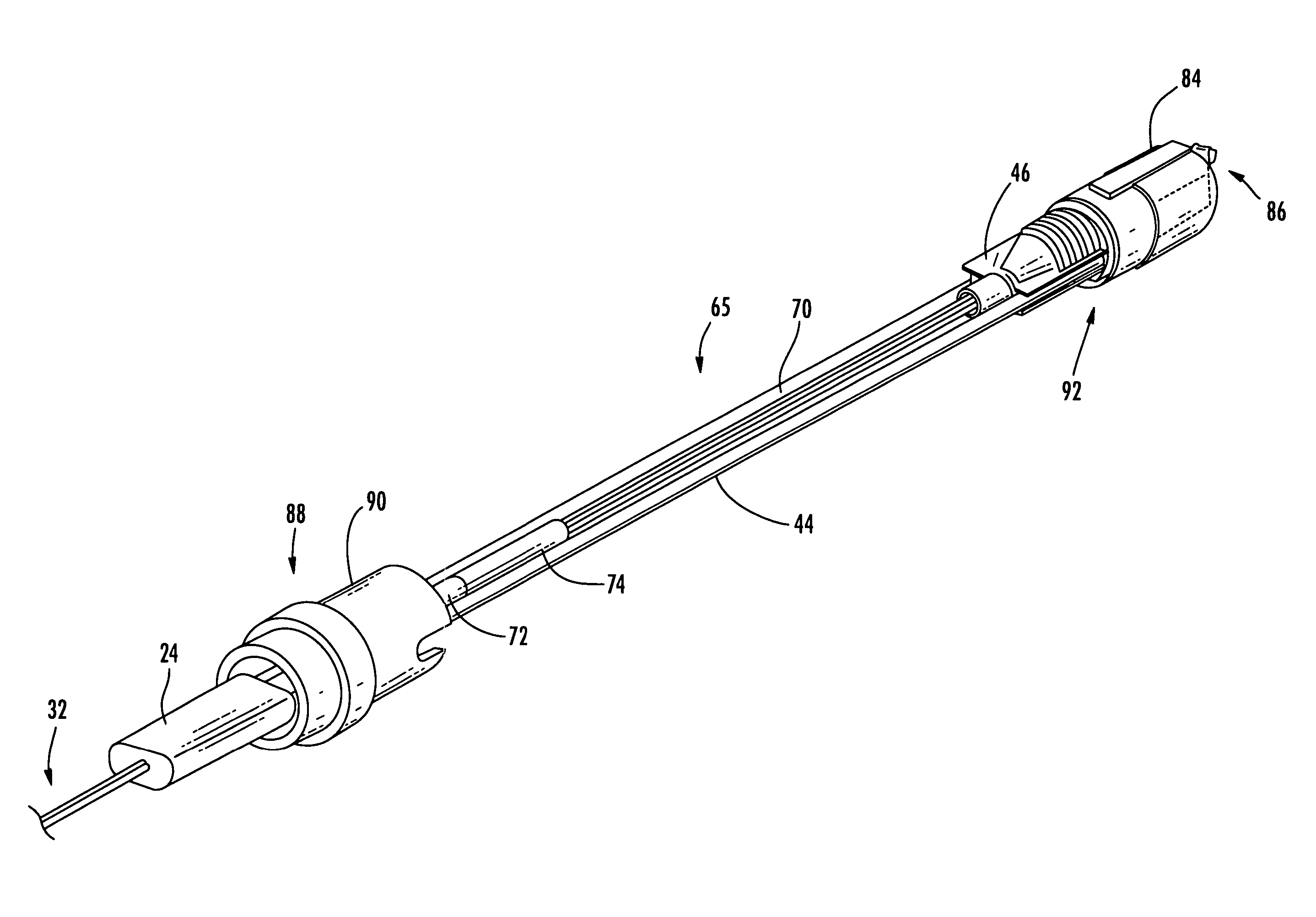
[0028]Reference will now be made to preferred embodiments of the present invention, examples of which are illustrated in the accompanying drawings. The present invention provides substantially flat drop cables with MT fiber optic connectors or plug assemblies that may quickly and easily be interconnected at a mid-span access location or at any other location in an optical network at which it is desired to use a drop cable. The present invention also provides substantially flat drop cables that have a stiffness that is low enough such that low-force polishing can be accomplished. The present invention further provides substantially flat drop cables that incorporate a minimum of relatively expensive strain relief material, while still limiting the amount of tension reaching a ferrule assembly when a cable is loaded.

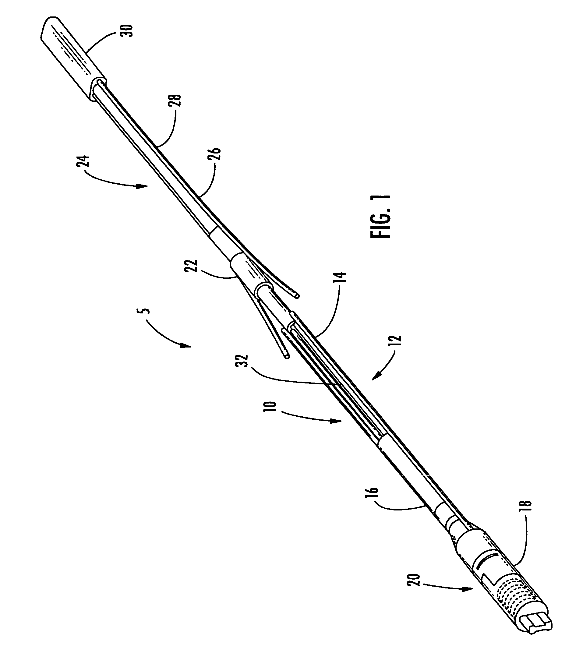
[0029]Referring to FIG. 1, in one exemplary embodiment, a substantially flat drop cable assembly 5 utilizes an overmolded furcation section 10 incorporating telescoping tub...


PUM


Abstract

A substantially flat fiber optic drop cable assembly comprises: a fiber optic connector comprising a fiber optic ferrule and a housing; a crimp body coupled to the housing of the fiber optic connector; a fiber optic cable comprising a pair of strength members disposed partially within the fiber optic cable; a first sheath disposed between the fiber optic connector and the fiber optic cable, the first sheath coupled to the crimp body; a second sheath disposed between the fiber optic connector and the fiber optic cable, the second sheath coupled to the fiber optic cable; and a demarcation element joining the first sheath and the second sheath, wherein the demarcation element comprises a substantially tubular element; wherein the pair of strength members are configured to engage the crimp body about the first sheath, the second sheath, and the demarcation element.

Description

CROSS-REFERENCE TO RELATED APPLICATION[0001]The present non-provisional patent application claims the benefit of priority of U.S. Provisional Patent Application No. 60 / 736,358, filed on Nov. 14, 2005, and entitled “Tether Installation at Demarcation Point,” the contents of which are incorporated in-full by reference herein.BACKGROUND OF THE INVENTION[0002]1. Field of the Invention[0003]The present invention relates generally to connectorized drop cables and methods for fabricating the same, and more specifically, to connectorized drop cables that may be readily interconnected with a mid-span access location of a fiber optic cable while including a demarcation point for isolating the connector from forces generated in the cable.[0004]2. Technical Background of the Invention[0005]Fiber optic networks are used to provide services from providers to subscribers over a vast network of optical signal carrying components. Within these networks, drop cables are often used to provide the end ...

Claims


Application Information

Patent Timeline
Patent Type & Authority Patents(United States)
IPC IPC(8): G02B6/44
CPCG02B6/4475H04M1/745
Inventor CODY, JOSEPH THALL, RADAWANLEWALLEN, CHRISTOPHER PAULLUTHER, JAMES P.
Owner CORNING OPTICAL COMM LLC
Why Eureka
Try Eureka