Hydraulic fluid dehydration system and method including pre-heating

a technology of hydraulic fluid and dehydrator, which is applied in the direction of membrane heating/cooling, separation processes, and pipes, etc., can solve the problems of reducing the life of bearings, so as to reduce the amount of feedback flow and increase the flow rate of hydraulic fluid through the dehydrator

Active Publication Date: 2008-07-24
PUTZMEISTER AMERICA
View PDF12 Cites 27 Cited by
  • Summary
  • Abstract
  • Description
  • Claims
  • Application Information

AI Technical Summary

Benefits of technology

[0014]To address the differences between the flow rate through the dehydrator and the flow rate from the fluid pump at relatively low temperatures of the hydraulic fluid, the dehydration system includes a fluid feedback line that returns a portion of the hydraulic fluid flow from the outlet of the fluid heater to the inlet of the fluid pump. Specifically, the system monitors the pressure of the hydraulic fluid entering into the dehydrator and opens a relief valve to allow a return flow of hydraulic fluid when the pressure at the inlet to the dehydrator exceed a threshold value. Thus, at relatively low temperatures for the hydraulic fluid, a significant portion of the hydraulic fluid flow leaving the fluid heater is returned to the inlet of the fluid pump. In this manner, the hydraulic fluid is recirculated through the fluid heater, thereby further elevating the temperature of the hydraul...

Problems solved by technology

It is widely recognized that the presence of water within the hydraulic fluid has a negative impact on the life of the oil, as well as components within the system.
It is well known that corrosion, oil oxidization, chemical wear and tear, reduced bearing fa...

Method used


Image

  • Hydraulic fluid dehydration system and method including pre-heating
  • Hydraulic fluid dehydration system and method including pre-heating
  • Hydraulic fluid dehydration system and method including pre-heating

Examples


Embodiment Construction

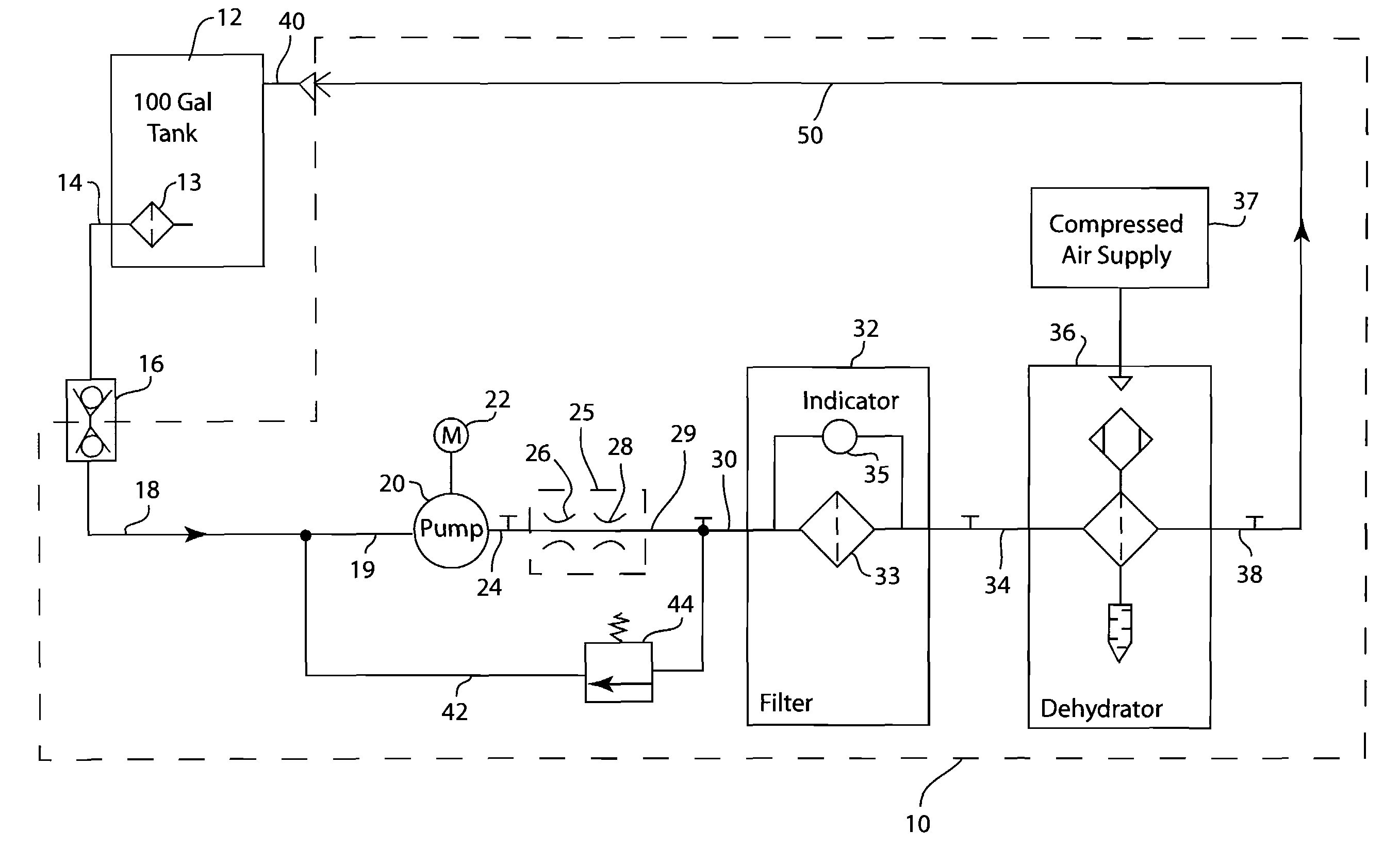
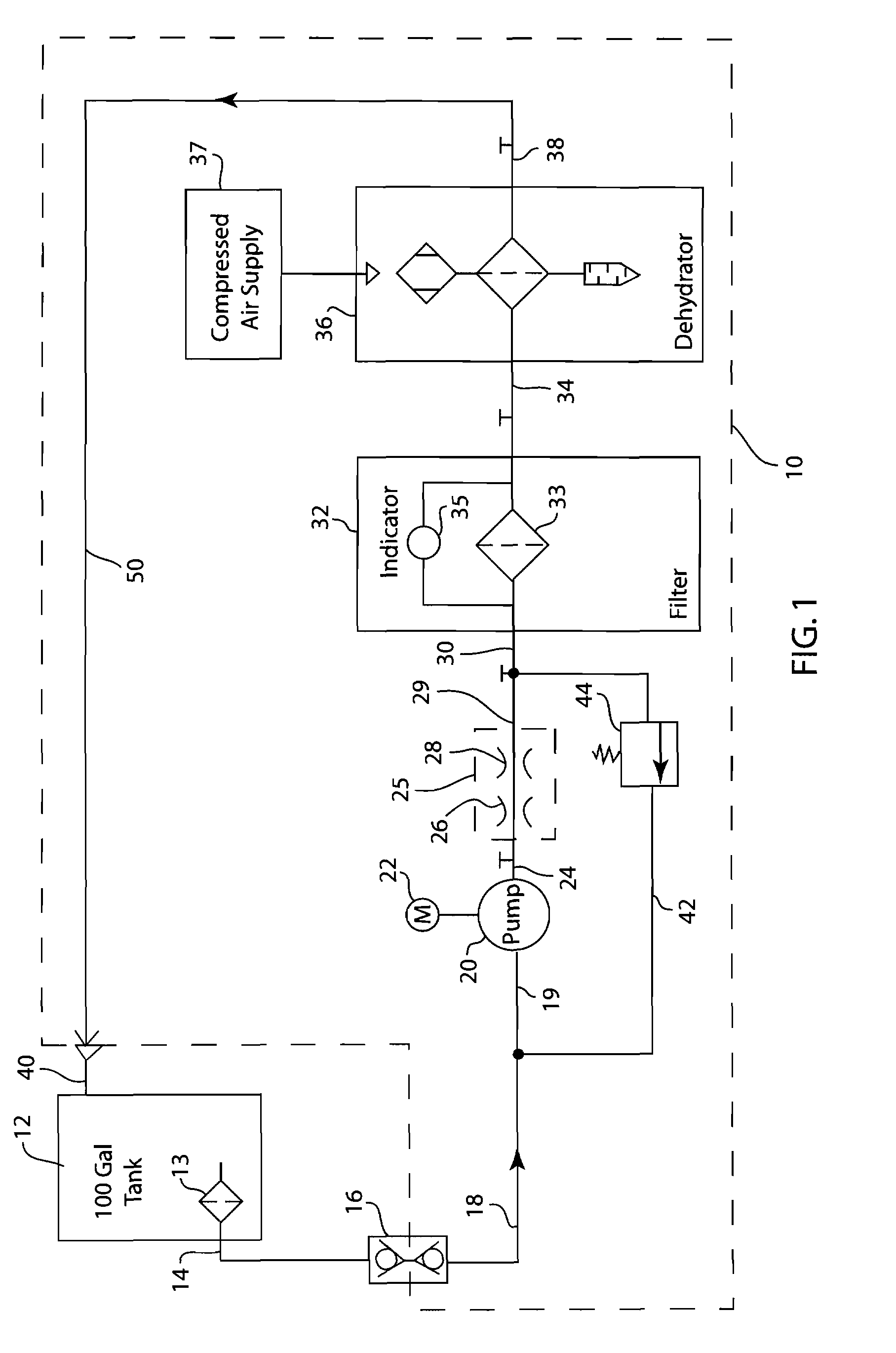
[0020]FIG. 1 is a schematic illustration of a system 10 that is operable to remove water from a supply of hydraulic fluid, such as oil. Throughout the following description, the term “hydraulic fluid” should be interpreted to include various fluids, such as oil. As shown in FIG. 1, the supply of hydraulic fluid is contained within a storage tank 12. In the embodiment illustrated, the storage tank 12 is a 100 gallon tank, although other size tanks are contemplated as being within the scope of the present invention. The storage tank 12 may be located on a large vehicle, such as a concrete pumping vehicle, that operates various components using pressurized hydraulic fluid. Alternatively, the storage tank 12 could be located at any location that hydraulic fluid or a similar fluid is required.

[0021]The storage tank 12 includes an internal filter 13 connected to an outlet 14 that is in fluid communication with the dehydration system 10 through a connector 16. The connector 16 is a standar...


PUM

PropertyMeasurementUnit
Pressureaaaaaaaaaa
Flow rateaaaaaaaaaa
Diameteraaaaaaaaaa

Abstract

A mobile dehydration system that is operable to remove water from a supply of fluid, such as hydraulic fluid. The mobile dehydration system includes a fluid pump that draws the supply of hydraulic fluid from a storage tank. The flow of hydraulic fluid passes through a fluid heater that elevates the temperature of the hydraulic fluid. The fluid heater includes at least one flow restricting orifice that reduces the pressure of the flow of hydraulic fluid, thereby elevating the temperature of the hydraulic fluid. The outlet of the fluid heater is connected to a dehydrator that removes water from the flow of hydraulic fluid. A fluid feedback line is connected between the outlet of the fluid heater and the inlet of the fluid pump to return a portion of the hydraulic fluid flow when the flow rate through the dehydrator is less than the flow rate from the fluid pump.

Description

CROSS REFERENCE TO RELATED APPLICATION(S)[0001]The present application is based on and claims priority to U.S. Provisional Patent Application Ser. No. 60 / 885,483, filed Jan. 18, 2007.BACKGROUND OF THE INVENTION[0002]The present invention generally relates to a system and method for removing water from a hydraulic fluid or oil. More specifically, the present invention relates to a system and method that receives a supply of hydraulic fluid and elevates the temperature of the hydraulic fluid above ambient to enhance the effectiveness of a dehydrator.[0003]During the operation of machinery powered by pressurized hydraulic fluid, such as oil, water can mix with the hydraulic fluid from ambient humidity, seal leaks, condensation or other sources near the work equipment. It is widely recognized that the presence of water within the hydraulic fluid has a negative impact on the life of the oil, as well as components within the system. It is well known that corrosion, oil oxidization, chemic...

Claims


Application Information

Patent Timeline
IPC IPC(8): F16L53/00E03B5/00F15B21/041
CPCB01D17/045B01D61/24F15B21/041C10N2240/08C10M175/0091C10M175/0025C10G33/06B01D61/36B01D2311/04B01D2311/103B01D2313/06B01D2313/24B01D2313/36B01D17/085B01D2311/14Y10T137/85978Y10T137/6416C10N2040/08
Inventor JOHNSON, CHARLES N.ZIMMERMANN, UWE E.FUNK, CARSTEN
Owner PUTZMEISTER AMERICA
Why Eureka
Try Eureka