Two piece stamped steel pulley

a two-piece, stamped technology, applied in the direction of gearing elements, belts/chains/gearings, hoisting equipments, etc., can solve the problems of inefficient use of raw materials, high cost of steel bars, so as to reduce the number of critical parts used in the manufacture of pulleys, reduce production costs, and reduce production costs

Inactive Publication Date: 2009-02-03
NIDEC MOTOR CORP
View PDF17 Cites 11 Cited by
  • Summary
  • Abstract
  • Description
  • Claims
  • Application Information

AI Technical Summary

Benefits of technology

[0016]By using stamped steel disks in the manufacture of the pulley of the present invention, the number of critical parts used in the manufacture of the pulley is minimized. The pulley formed in this manner provides a simpler method of manufacture that incorporates less operations and less assembly. By eliminating the operations and parts, the quality costs associated with the manufacture of conventional pulleys may be reduced.

Problems solved by technology

However, pulleys produced from this type of machining are expensive since the machining operations for forming a pulley generally have long cycle times and tend to generate high percentages of scrap.
Generally speaking, this process does not efficiently use the raw material since a large portion of the material is machined away as chips.
Additionally, bar stock is a relatively expensive form of material, and pulleys formed from bar stock tend to be rigid such that they are harder to install in the appliance.
However, plastic pulleys formed in this manner often have strength and wear problems in these applications such that their use is limited.
The powdered metal sintered hub is expensive to form and the center hole must be extruded and reamed to the required dimensions to fit on the shaft with minimal slip.
Additionally, the assembly operation associated with arranging the pieces around the hub is time consuming and costly, and an inventory of circular pieces and hubs must be maintained in the proper ratios to maintain efficient production on assembly lines.
However, since the filing of the parent application it has been observed that many of the mechanical fastener connections between the two stamped pulley halves do not work well in an environment where the pulley is rotated by a belt wrapped around the pulley.
Where the two pulley halves are attached by mechanical fasteners, and in particular where the fasteners are tabs formed on each of the pulley halves that are inserted through slots in the other pulley half and bent over, the axial force tends to straighten the bends in the tabs causing the two pulley halves to be separated from each other resulting in a failure of the pulley.

Method used


Image

  • Two piece stamped steel pulley
  • Two piece stamped steel pulley
  • Two piece stamped steel pulley

Examples


Embodiment Construction

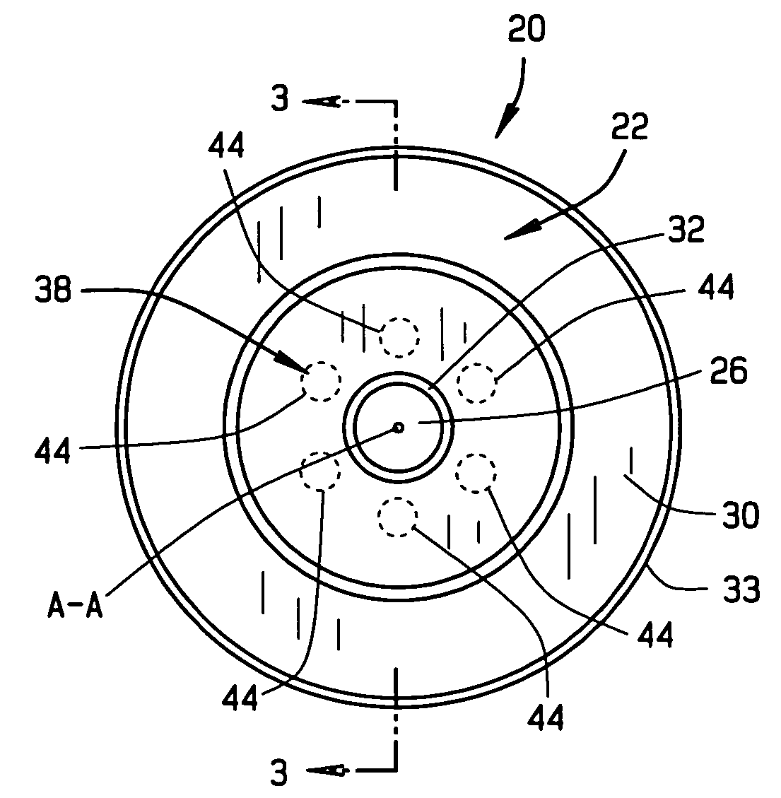
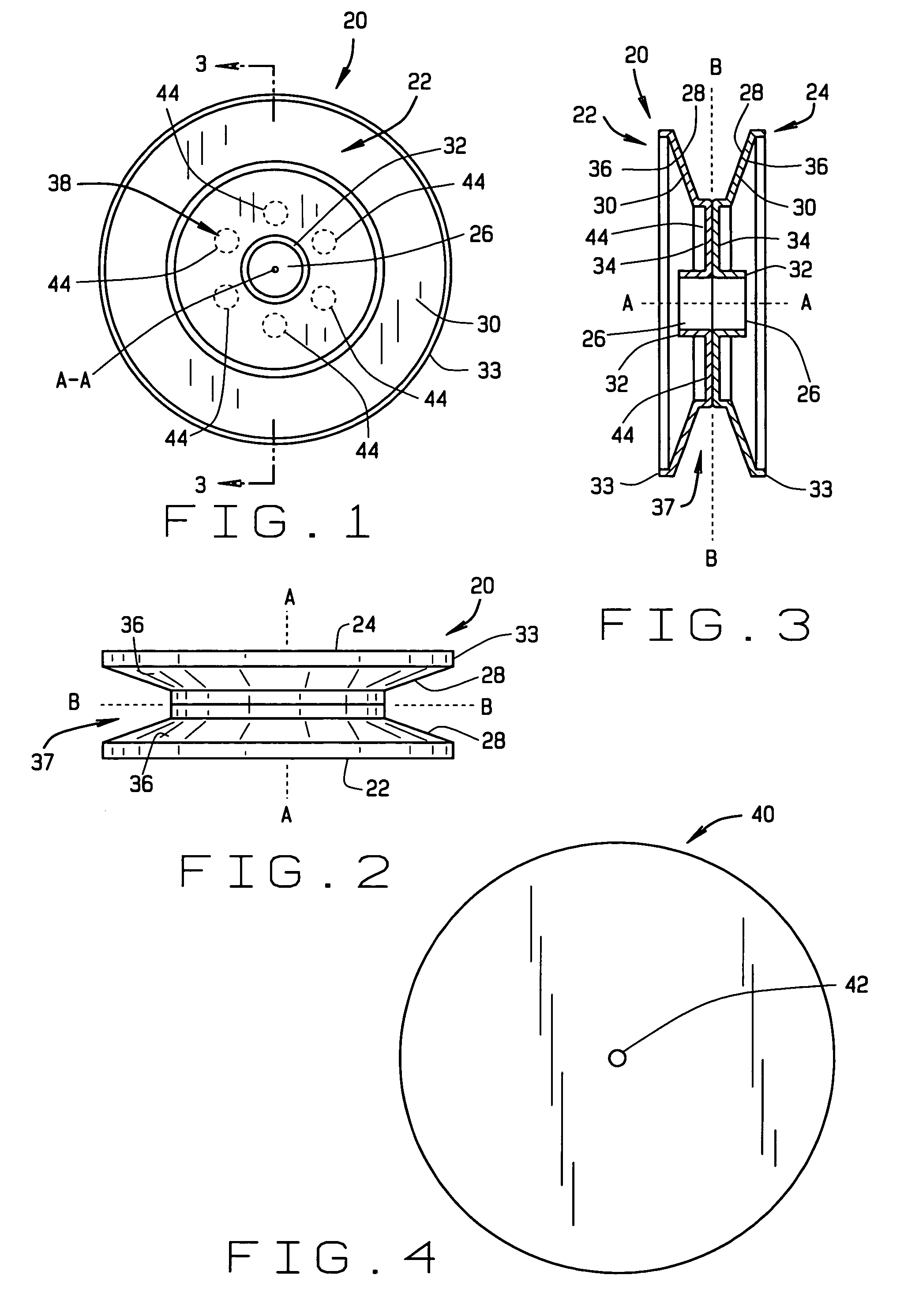
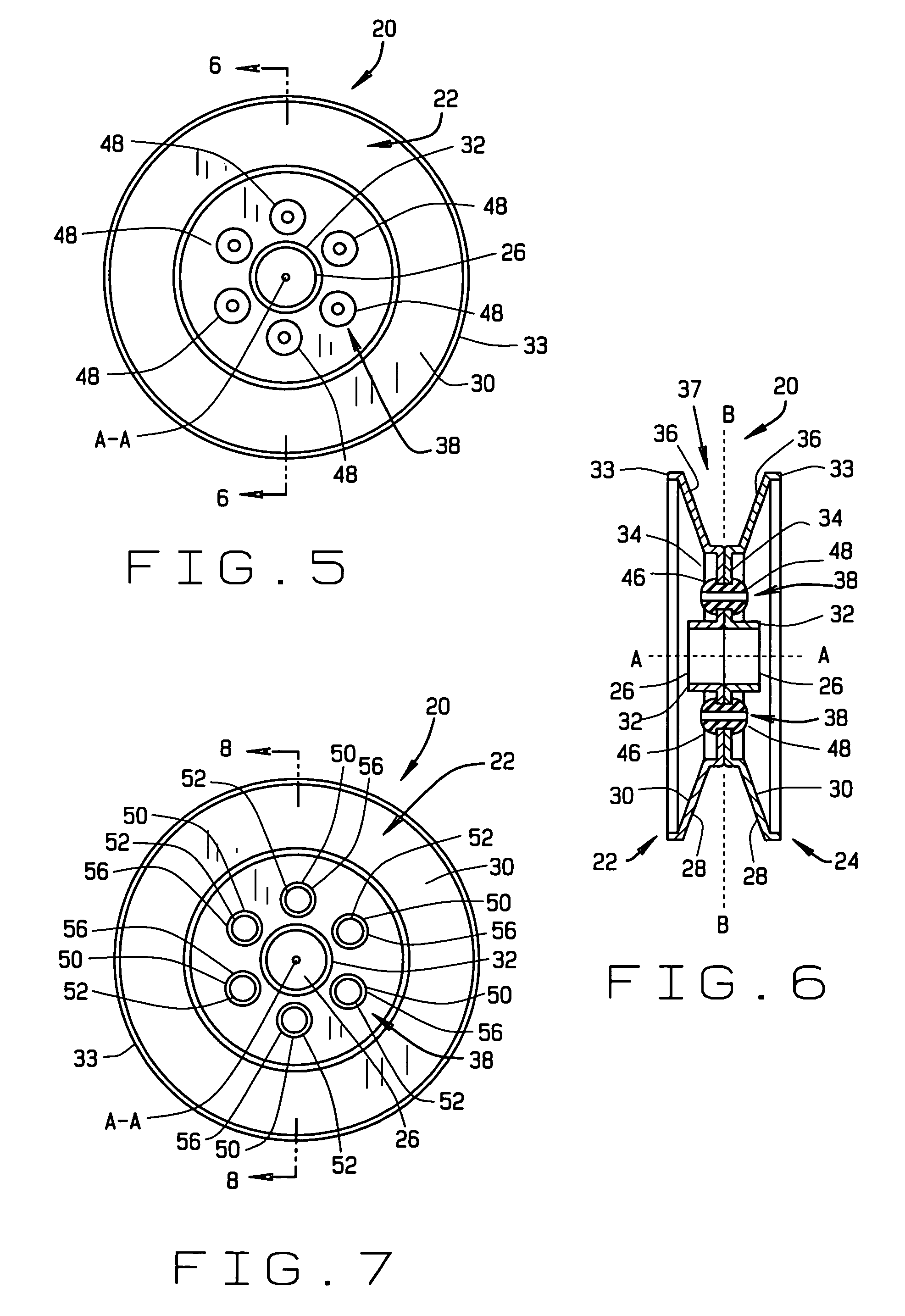
[0032]FIGS. 1-3 show the general arrangement of a pulley 20 of the present invention. The pulley 20 has first and second identical disks 22,24 positioned in a side-by-side arrangement and attached together to form the pulley 20. Each of the disks 22,24 has a center hole 26, and a center axis A-A through the center hole 26 about which the disk rotates when formed into the pulley 20. Each of the disks has an inner side surface 28 and outer side surface 30. For this description, the outer side 30 is that side of the disk exposed from the pulley when the disks 22,24 are arranged side-by-side, and the inner side 28 is that side of each disk placed adjacent each other when the disks 22,24 are arranged side-by-side.

[0033]In the area surrounding the center hole 26, each of the disks 22,24 has a cylindrical hub 32 that is concentric with the disk center hole 26 and center axis A-A. The hub 32 extends outward and away from the outer side 30 of each respective disk along the disk center axis A...


PUM


Abstract

A pulley is provided with first and second disks each having an outer surface and an inner surface, and a center hole with a center axis. Each disk has a hub formed at its center hole that extends outwardly from the disk outer surface. The inner side of each disk has a drive surface and a connection surface extending around its respective center hole. The connection surface is perpendicular to the center axis and the drive surface is angled relative to the connection surface to form the outer surface of each disk with a generally concave shape. The connection surfaces of the first and second disks are abutted and secured together using a fastening mechanism. The disks are arranged where the drive surfaces form an annular groove around the hubs and the hubs of each disk are aligned concentrically with the groove.

Description

[0001]This patent application is a continuation-in-part of patent application Ser. No. 09 / 669,144 titled “Two Piece Stamped Steel Pulley,” filed Sep. 26, 2000 and now abandoned.BACKGROUND OF THE INVENTION[0002](1) Field of the Invention[0003]This invention pertains to a pulley commonly used in consumer appliances, such as washing machines and dishwashers. Specifically, the invention pertains to a novel design of the pulley and a method of making the same.[0004](2) Description of the Related Art[0005]Pulleys are commonly found in many applications where the rotary motion between two shafts is coupled together through a pulley and belt system. Many consumer appliances, such as washing machines and dishwashers, commonly have several pulleys in their drive systems to transfer the rotary motion of the drive motor to pumps, transmissions, and other devices requiring power coupled from the motor. Because of mass production of these consumer appliances, the number of pulleys required in pro...

Claims


Application Information

Patent Timeline
Patent Type & Authority Patents(United States)
IPC IPC(8): F16H55/36F16H55/44
CPCF16H55/44
Inventor FADLER, RICHARD J.AHAUS, LOREN A.LEICHT, JEFFREY K.
Owner NIDEC MOTOR CORP
Why Eureka
Try Eureka