Systems and methods for reducing noise during video deinterlacing

a technology of video deinterlacing and noise reduction, applied in the field of video processing techniques, to achieve the effect of removing noise without adversely affecting the appearance of moving display objects

Inactive Publication Date: 2009-05-26
INTEGRATED DEVICE TECH INC
View PDF35 Cites 18 Cited by
  • Summary
  • Abstract
  • Description
  • Claims
  • Application Information

AI Technical Summary

Benefits of technology

[0012]Embodiments of the present principles advantageous support the efficient generation of frames of progressive scan video data from fields of interlaced video data with the creation of a minimal number of artifacts. In particular, systems and methods embodying these principles discriminate between noise and a

Problems solved by technology

Furthermore, these systems and methods also discriminate between noise and display obj

Method used


Image

  • Systems and methods for reducing noise during video deinterlacing
  • Systems and methods for reducing noise during video deinterlacing
  • Systems and methods for reducing noise during video deinterlacing

Examples


Embodiment Construction

[0020]The principles of the present invention and their advantages are best understood by referring to the illustrated embodiment depicted in FIGS. 1-5 of the drawings, in which like numbers designate like parts.

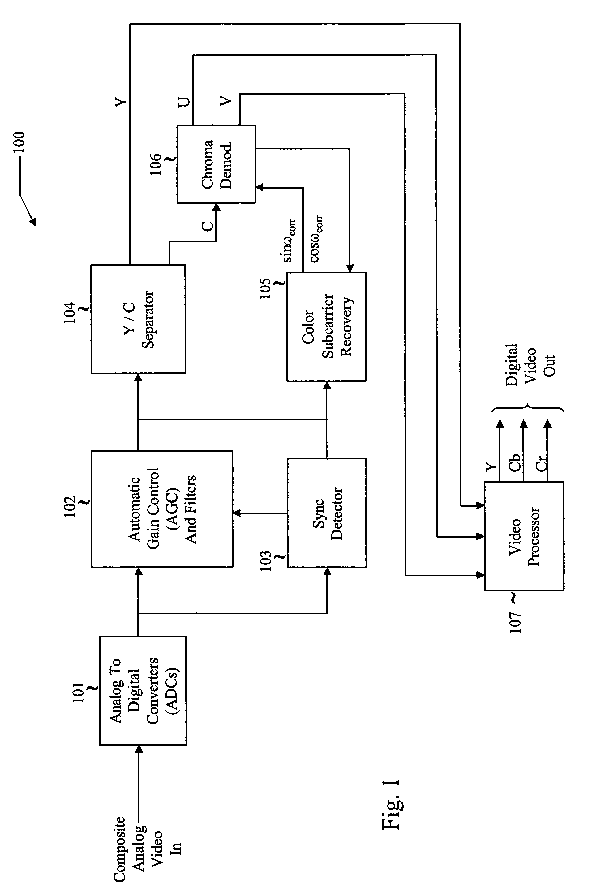
[0021]FIG. 1 is a diagram of an exemplary analog to digital video decoder 100 suitable for describing the principles of the present invention. In the illustrated embodiment, video encoder converts a composite analog video input signal, in the YC format, into digital video data in the YCrCb component video format, although the inventive principles are not necessarily limited thereto.

[0022]In video encoder 100, the composite analog input video is converted into composite digital video in the YC format by analog to digital converters (ADCs) 101. The digitized YC video data are then passed through automatic gain control (AGC) and filters block 102. A sync detector 103 detects the vertical synchronization (VSYNC) signal, which controls the timing of the playback of each display f...


PUM


Abstract

A method of deinterlacing includes generating a deinterlaced display frame including a reference field of lines of display pixels of a first parity and a generated field of lines of display pixels of a second parity. A frame motion map is generated which includes bits representing a presence of motion or an absence of motion at the display pixels of the reference and generated fields. Testing is performed for the presence of motion or the absence of motion at a selected display pixel of the reference field utilizing the frame motion map. In response to detecting a presence of motion at the selected display pixel of the referenced field, replacing a pixel value corresponding to the selected display pixel with a pixel value generated by interpolating between display pixel values corresponding to neighboring display pixels in the generated field.

Description

CROSS REFERENCE TO RELATED APPLICATION[0001]The following co-pending and co-assigned applications contain related information and are hereby incorporated by reference:[0002]Ser. No. 11 / 167,756 by Pillay, Bounds and Gallagher entitled CIRCUITS AND METHODS FOR DETECTING 2:2 ENCODED VIDEO AND SYSTEMS UTILIZING THE SAME, filed Jun. 27, 2005, now U.S. Pat. No. 7,450,184;[0003]Ser. No. 11 / 167,877 by Pillay, Bounds and Gallagher entitled CIRCUITS AND METHODS FOR DEINTERLACING VIDEO DISPLAY DATA AND SYSTEMS USING THE SAME, filed Jun. 27, 2005;[0004]Ser. No. 11 / 167,682 by Pillay, Bounds and Gallagher entitled SYSTEMS AND METHODS FOR DETECTING A CHANGE IN A SEQUENCE OF INTERLACED DATA FIELDS GENERATED FROM A PROGRESSIVE SCAN SOURCE, filed Jun. 27, 2005, now U.S. Pat. No. 7,420,626; and[0005]Ser. No. 11 / 172,323 by Gallagher, Bounds and Pillay entitled SYSTEMS AND METHODS FOR DISPLAY OBJECT EDGE DETECTION AND PIXEL DATA INTERPOLATION IN VIDEO PROCESSING SYSTEMS, filed Jun. 30, 2005, now U.S. Pa...

Claims


Application Information

Patent Timeline
IPC IPC(8): H04N5/14H04N17/00H04N5/21
CPCH04N7/012H04N7/0137
Inventor PILLAY, SANJAY R.BOUNDS, BRIAN F.GALLAGHER, WILLIAM LYNN
Owner INTEGRATED DEVICE TECH INC
Why Eureka
Try Eureka