Multistage turbocompressor

a turbocompressor and multi-stage technology, applied in the direction of combustion engines, non-positive displacement fluid engines, steam engine plants, etc., can solve the problem of additional installation spa

Active Publication Date: 2009-07-14
MAN ENERGY SOLUTIONS SA
View PDF27 Cites 12 Cited by
  • Summary
  • Abstract
  • Description
  • Claims
  • Application Information

AI Technical Summary

Benefits of technology

[0004]The object of the present invention is to design a multistage turbocompressor with integrated gear such that a compact arrangement of a line of machines consisting of a turbocompressor and drive unit is possible.
[0006]A line of machines, in which a common central plane is present for the turbocompressor and the drive unit, can be set up by means of the multistage turbocompressor designed according to the present invention. If this line of machines is expanded by additional units, such as, for example, a motor / generator and / or an expander, then the common central plane is available for the additional units as well. By means of the common central plane, a height offset in the base frame, on which the units are assembled, as well as in the foundation bed (steel framing or concrete) of the line of machines is avoided. The space required for the installation of the line of machines becomes smaller, as a result of which the production, transportation, operation and maintenance of the line of machines become simpler and more cost-favorable. The construction of larger compressors becomes possible, since the space required for the compressor housing is increased. Finally, the mechanical strain on the individual components, such as the driving pinion, the bearing and the gear housing, is reduced.

Problems solved by technology

Consequently, additional space is required for installation.

Method used


Image

  • Multistage turbocompressor
  • Multistage turbocompressor
  • Multistage turbocompressor

Examples


Embodiment Construction

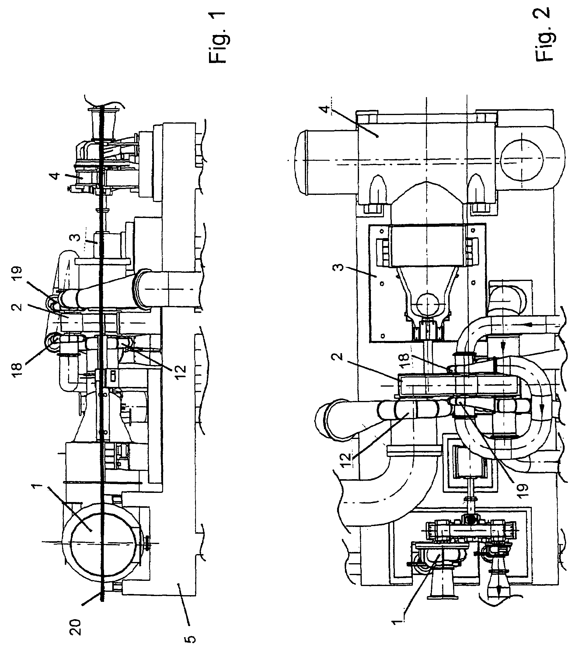
[0015]Referring to the drawings in particular, the line of machines shown in FIG. 1 is part of a chemical plant for the treatment and the further processing of gases. Such a line of machines comprises a drive unit 1 and a geared compressor 2. Depending on the type of the chemical plant, the line of machines may comprise a motor / generator 3 and an expander 4 as well. The individual units are coupled to one another and are mounted on a base frame, the machine bed 5, which rests on a concrete or steel foundation. A plurality of coolers, a condenser and additional apparatuses needed for the operation of the plant are located under the machine bed 5.

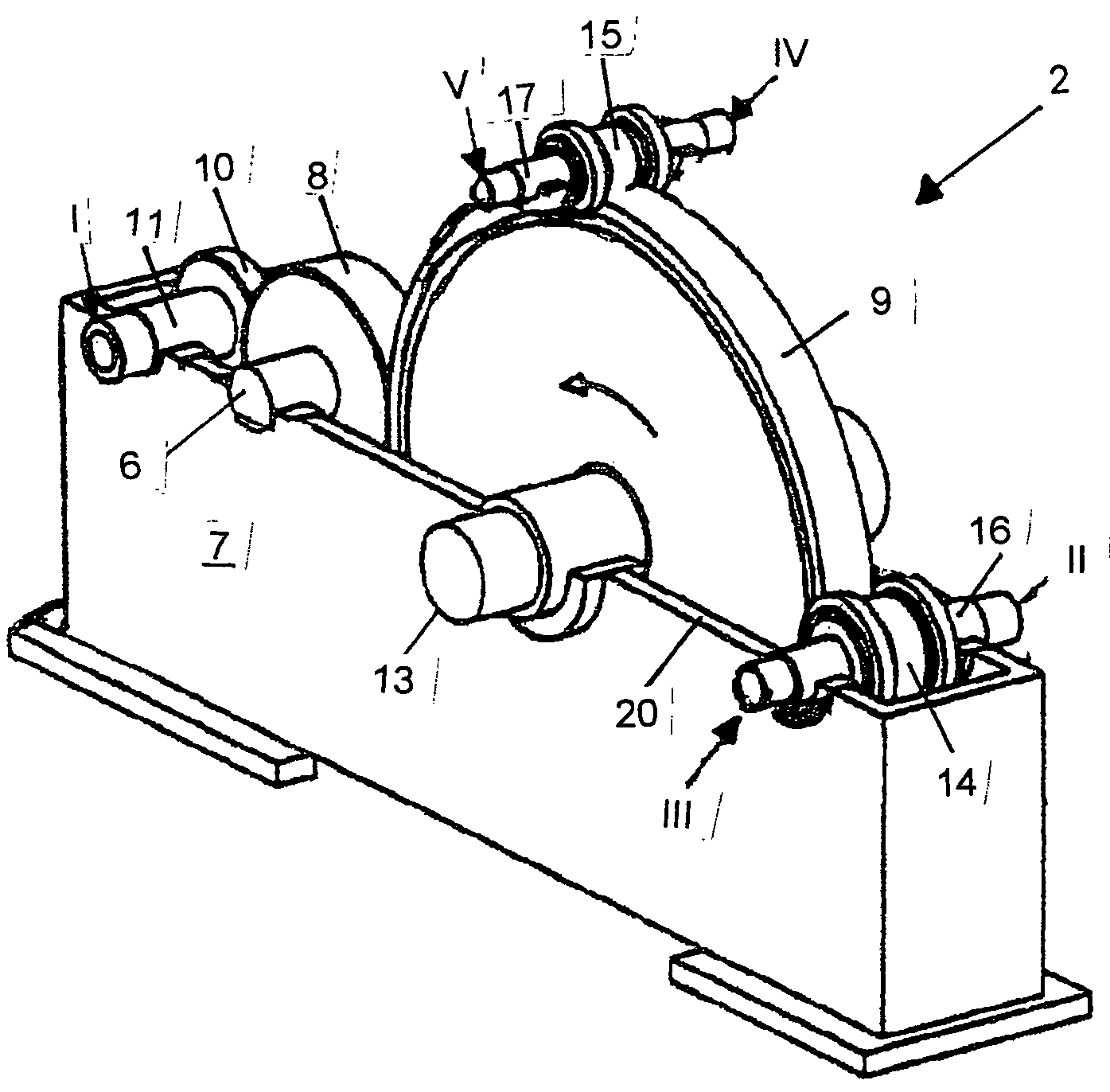
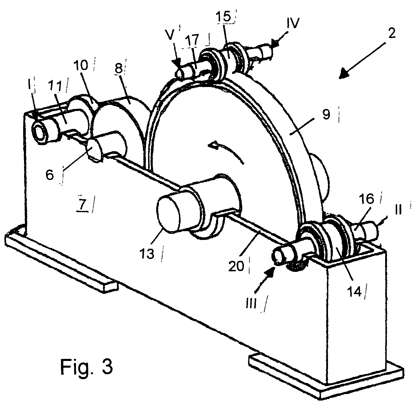
[0016]The drive unit 1 is preferably embodied as a steam turbine, whose driven shaft is connected to the driving shaft 6 of the following geared compressor 2. The geared compressor 2 is a multistage turbocompressor with integrated gear and is used for compressing a gas.

[0017]The geared compressor 2 according to FIG. 3 comprises a housing 7, i...


PUM


Abstract

A multistage turbocompressor, designed as a geared compressor with an integrated gear, contains a central greater wheel (9) that meshes with a plurality of pinions (14, 15), wherein each pinion (14, 15) is mounted, in a manner adapted to rotate in unison, on a pinion shaft (16, 17). A bladed wheel of a compressor stage (II, III, IV, V) is arranged on the ends of each of the pinion shafts. The greater wheel (9) meshes with a driving pinion (8), which is mounted, in a manner adapted to rotate in unison, on a driving shaft 6 connected to a drive unit (1). The axis of the driving pinion (8) is arranged, with the axis of the greater wheel (9), in the same horizontal plane (20), and the driving pinion (8) meshes with a pinion (10) of a first compressor stage (I) mounted, in a manner adapted to rotate in unison, on a pinion shaft (11).

Description

CROSS REFERENCE TO RELATED APPLICATIONS[0001]This application claims the benefit of priority under 35 U.S.C. § 119 of German Patent Application DE 10 2005 002 702.4 filed Jan. 19, 2005, the entire contents of which are incorporated herein by reference.FIELD OF THE INVENTION[0002]The present invention pertains to a multistage turbocompressor, which is designed as a geared compressor with an integrated gear, with the features of the preamble of claim 1.BACKGROUND OF THE INVENTION[0003]Prior-art geared compressors (DE 974 418, EP 0 440 902 B1, EP 1 302 668 A1) are characterized by a greater wheel that meshes with a plurality of pinions. One or two compressor stages are each fastened to the pinions. The pinions surround the greater wheel, which is driven directly, as the shaft of the greater wheel is coupled with the driving shaft. Another possibility of coupling the drive unit to the geared compressor may take place via a driving pinion, which, like the pinions of the compressor stages...

Claims


Application Information

Patent Timeline
Patent Type & Authority Patents(United States)
IPC IPC(8): F02B33/44
CPCF04D25/163
Inventor RODEHAU, MICHAELANDRES, WULF-DIRKTHIEME, KLAUS
Owner MAN ENERGY SOLUTIONS SA
Why Eureka
Try Eureka