Throttle valve controller and engine

a throttle valve and controller technology, applied in the direction of electric control, machine/engine, fuel injection control, etc., can solve the problems of insufficient air supply for stable combustion, the throttle valve is left open, and the rider feels discomfort during the rid

Inactive Publication Date: 2009-08-11
KAWASAKI HEAVY IND LTD
View PDF23 Cites 3 Cited by
  • Summary
  • Abstract
  • Description
  • Claims
  • Application Information

AI Technical Summary

Benefits of technology

[0013]In such a construction, since the movable stopper is retracted in the closing direction of the throttle valve on the rotational track of the contact portion, the movable stopper can be maintained in the restricting state so as to increase a rotational range of the input member in the closing direction of the throttle valve. Therefore, the rotational range of the input member in the closing direction of the throttle valve can be suitably changed.
[0017]In such a construction, since the movable stopper is configured to mechanically stop or release the stopper portion in or from the retracted state independently of an electric system, it can be extended or retracted stably without being negatively affected by electric or software errors.
[0019]In such a construction, since the movable stopper is configured to hydraulically stop or release the stopper portion in or from the retracted state independently of the electric system, it can be extended or retracted stably without being negatively affected by electric or software errors and substantially without occurrence of mechanical wear, etc.
[0032]According to another aspect of the present invention, there is provided an engine comprising a throttle valve controller configured to control opening and closing of a throttle valve disposed in an air-intake passage of a throttle body coupled to the engine, the throttle valve controller including an input member that is rotatable in association with a rider's hand operation; a power transmission device with an input part thereof coupled to the input member; an output member that is coupled to an output part of the power transmission device and causes the throttle valve to rotate in association therewith; an actuator configured to drive the power transmission device to cause the output member to rotate relative to the input member to change a rotational ratio of the output member to the input member independently of the hand operation; and a movable stopper configured to change and restrict a rotational range of the input member in closing direction of the throttle valve.

Problems solved by technology

If a change amount in an opening degree of the throttle valve in response to the rider's throttle grip operation is large, then the amount of air varies significantly, causing the rider to feel discomfort during travel of the motorcycle.
If the rider quickly closes the throttle grip to close the throttle valve, then the amount of air becomes insufficient for stable combustion.
However, if the motor does not correctly operate and unexpectedly stops in a state where the throttle valve is driven to be opened by the motor, then the throttle valve will be left open by an excess phase angle due to the stopping of the motor.
As a result, gas exhausting efficiency and fuel consumption efficiency decrease.

Method used


Image

  • Throttle valve controller and engine
  • Throttle valve controller and engine
  • Throttle valve controller and engine

Examples


embodiment 1

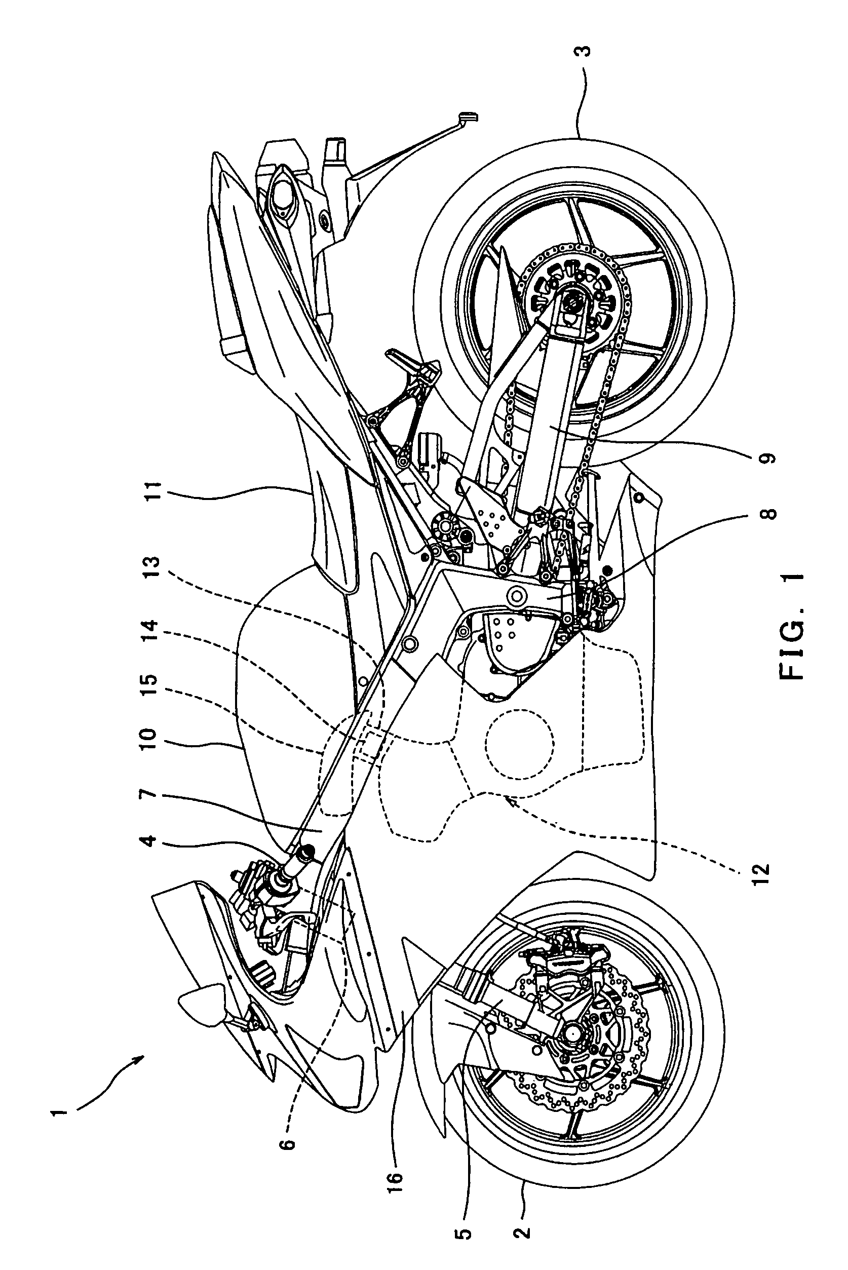
[0059]FIG. 1 is a side view of a motorcycle 1 equipped with a throttle valve controller 14 according to a first embodiment of the present invention. The motorcycle 1 is a road sport type motorcycle in which a rider (not shown) rides with an upper body leaning forward. Turning now to FIG. 1, the motorcycle 1 includes a front wheel 2 and a rear wheel 3. The front wheel 2 is rotatably mounted to a lower end portion of a front fork 5 extending substantially vertically. The front fork 5 is mounted on a steering shaft (not shown) by an upper bracket (not shown) attached to an upper end thereof, and an under bracket located below the upper bracket. The steering shaft is rotatably supported by a head pipe 6. A bar-type steering handle 4 extending in a rightward and leftward direction is attached to the upper bracket. When the rider rotates the steering handle 4 clockwise or counterclockwise, the front wheel 2 is turned to a desired direction around the steering shaft.

[0060]A pair of right a...

example 1

Alternative Example 1

[0078]Subsequently, a first alternative example of a movable stopper applicable to the throttle valve controller 14 of the first embodiment will be described. FIG. 6A is a cross-sectional view showing an extended state of a movable stopper 65 according to the first alternative example of the first embodiment. FIG. 6B is a cross-sectional view showing a retracted state of the movable stopper 65 according to the first alternative example. As shown in FIG. 6A, the movable stopper 65 has a housing 66 fixed at a predetermined location, into which a rear portion of a stopper portion 67 is inserted. The housing 66 has a penetrating hole 66a that opens toward the contact portion 25a of the throttle pulley 25, a large-diameter portion 66b which is a space having a diameter larger than that of the penetrating hole 66a, and a small-diameter concave portion 66c that is coaxial with the penetrating hole 66a and has a diameter smaller than that of the large-diameter portion 6...

example 2

Alternative Example 2

[0082]Subsequently, a second alternative example of a movable stopper applicable to the throttle valve controller 14 of the first embodiment will be described. FIG. 7A is a cross-sectional view showing an extended state of a movable stopper 75 according to the second alternative example of the first embodiment. FIG. 7B is a cross-sectional view showing a retracted state of the movable stopper 75 according to the second alternative example. As shown in FIG. 7A, the movable stopper 75 has a stopper portion 77 movably inserted into a hydraulic cylinder 76. The hydraulic cylinder 76 has a first hydraulic passage 81 into which the stopper portion 77 is inserted, and a second hydraulic passage 82 into which a return piston 78 is inserted. The first hydraulic passage 81 and the second hydraulic passage 82 are connected to each other through a first relief valve 79 and a first communication passage 83. Actuation of the first relief valve 79 causes oil to flow from the f...


PUM


Abstract

A throttle valve controller configured to control opening and closing of a throttle valve disposed in an air-intake passage of a throttle body coupled to an engine, including an input member that is rotatable in association with a rider's hand operation, a power transmission device with an input part thereof coupled to the input member, an output member that is coupled to an output part of the power transmission device and causes the throttle valve to rotate in association therewith, an actuator configured to drive the power transmission device to cause the output member to rotate relative to the input member to change a rotational ratio of the output member to the input member independently of the hand operation, and a movable stopper configured to change and restrict a rotational range of the input member in a closing direction of the throttle valve.

Description

TECHNICAL FIELD[0001]The present invention relates to a throttle valve controller that is configured to control opening and closing of a throttle valve disposed in an air-intake passage of a throttle body coupled to an engine, and the engine.BACKGROUND ART[0002]In conventional motorcycles, a throttle body is coupled to an intake port of an engine, and a butterfly throttle valve disposed in an air-intake passage of the throttle body is controlled to be opened and closed, thereby controlling an amount of air taken in from outside and supplied to the engine. The throttle valve is opened and closed in association with a rider's hand operation of a throttle grip of the motorcycle. If a change amount in an opening degree of the throttle valve in response to the rider's throttle grip operation is large, then the amount of air varies significantly, causing the rider to feel discomfort during travel of the motorcycle. If the rider quickly closes the throttle grip to close the throttle valve,...

Claims


Application Information

Patent Timeline
Patent Type & Authority Patents(United States)
IPC IPC(8): F02D9/02F02D11/10F02D41/00
CPCF02D9/1065F02D11/10F02D11/04F02B61/02F02D9/1095
Inventor FUKAMI, YOJISAKANAKA, SATORUHIROKAMI, TATSUYAYAZAKI, MITSUHIRO
Owner KAWASAKI HEAVY IND LTD
Why Eureka
Try Eureka