Magnetic field probe apparatus and a method for measuring magnetic field

a magnetic field and probe apparatus technology, applied in the direction of magnetic field measurement using galvano-magnetic devices, voltage/current isolation, instruments, etc., can solve the problems of reducing the spatial resolution of measurement, affecting the sensitivity of the measuring system as a whole, and the complexity of the measuring system, so as to achieve the reduction of the impedance of the loop-like conductor, the effect of reducing the voltage drop across the loop-like conductor and reducing the sensitivity

Inactive Publication Date: 2009-09-29
HITACHI LTD
View PDF9 Cites 10 Cited by
  • Summary
  • Abstract
  • Description
  • Claims
  • Application Information

AI Technical Summary

Benefits of technology

[0009]According to this invention, one end of the loop-like conductor in which the voltage corresponding to the magnetic field to be measured is induced, is connected with the signal line side or the ground (GND) line side of a pair of feeder lines connected with a measuring device, while the other end of the loop-like conductor is not connected with the remaining feeder line but disposed in such a manner that an electric capacitance is formed between this other end and one (i.e. signal line side or GND line side) of the feeder lines. The shape of the loop-like conductor and the electric capacitance are so adjusted that the series resonance frequency specified by the capacitance and the inductance of the loop-like conductor may become equal to a predetermined measurement frequency. With this type of magnetic field probe, the impedance of the loop-like conductor can be minimized by virtue of the series resonance due to the combined effect of the inductance of the loop-like conductor and the capacitance formed between the intended end of the loop-like conductor and one of the feeder lines. As a result, the voltage drop across the loop-like conductor can be minimized. Thus, the magnetic field probe according to this invention can achieve a measurement with a higher sensitivity as compared with the conventional counterpart when measurement is performed on magnetic field having the same frequency as the series resonance frequency mentioned above.

Problems solved by technology

However, the increase in the loop size of the antenna causes the decrease in the spatial resolution in measurement.
This may cause a problem that the sensitivity to magnetic field of the measuring system as a whole degrades.
Thus, the measuring system incurs complexity.

Method used


Image

  • Magnetic field probe apparatus and a method for measuring magnetic field
  • Magnetic field probe apparatus and a method for measuring magnetic field
  • Magnetic field probe apparatus and a method for measuring magnetic field

Examples


Embodiment Construction

[0027]Embodiments of this invention will now be described with reference to the attached drawings in the following.

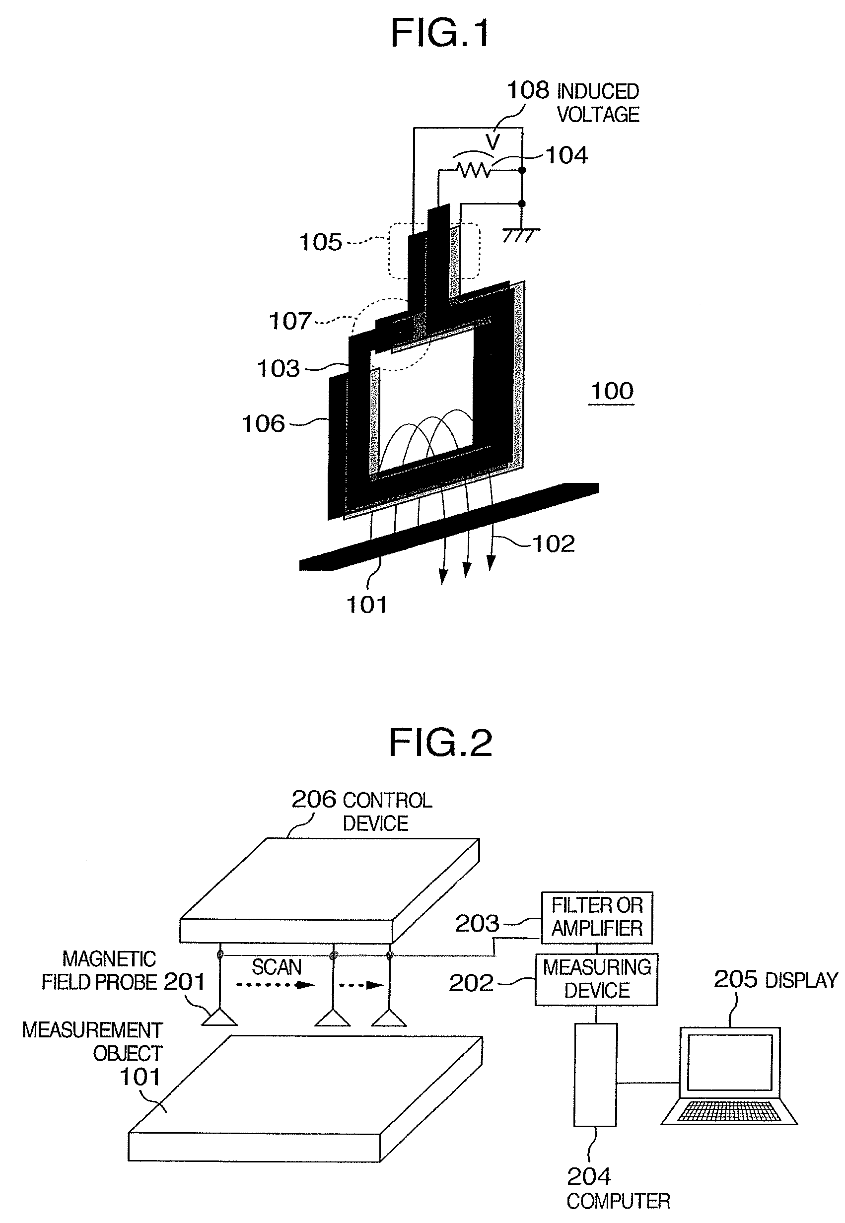
[0028]FIG. 1 shows a model structure of a magnetic field probe as an embodiment of this invention, for measuring the intensity, phase and orientation of the magnetic field 102 developed by such a measurement object 101 as the housing of an electronic device, a printed circuit board (PCB), a large-scale integrated (LSI) circuit or wiring conductors.

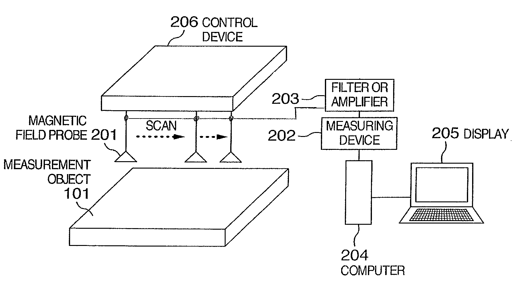
[0029]FIG. 2 schematically shows a model structure of a measuring apparatus for locating the radiation source of electromagnetic energy in or around a measuring object 101 through the measurement of the spatial distribution of the intensity, phase and orientation of the magnetic field 102 generated by the measurement object 101 by using a magnetic field probe.

[0030]The measuring apparatus as shown in FIG. 2 may have different names such as a magnetic field probe apparatus, a magnetic field measuring apparatus, a magnetic field...


PUM


Abstract

A magnetic field probe apparatus includes a loop-like conductor and feeder lines spaced at a distance from the loop-like conductor. The shape of the loop-like conductor and the arrangement of the feeder lines are adjusted in such a manner that the resonance frequency determined by the combination of the inductance of the loop-like conductor line and the capacitance formed between the looped-conductor and the feeder lines, is matched to the frequency of the magnetic field generated by and in the vicinity of a measurement object (e.g. electronic device) or the frequency of the electric signal which generates the magnetic field. With the magnetic field probe apparatus according to this invention, the magnetic field in the vicinity of the measurement object can be measured with high sensitivity.

Description

INCORPORATION BY REFERENCE[0001]The present application claims priority from Japanese application JP2006-005483 filed on Jan. 13, 2006, the content of which is hereby incorporated by reference into this application.BACKGROUND OF THE INVENTION[0002]This invention relates to an apparatus and a method for measuring the spatial distribution of the intensity, phase and orientation of the magnetic field generated in or around an electronic device.[0003]The technique of measuring the spatial distribution of magnetic field in the vicinity of an electronic device is useful in locating the source of the current attributable to unwanted electromagnetic radiations (known as electromagnetic interference) or the cause of electromagnetic interference attributable to mutual interference between different electronic devices that gives rise to erroneous operations or degraded performances of the electronic devices.[0004]The inventors of this invention have already developed such magnetic field probes...

Claims


Application Information

Patent Timeline
Patent Type & Authority Patents(United States)
IPC IPC(8): G01R33/00G01R31/02
CPCG01R29/0871G01R33/06G01R29/0878G01R15/20
Inventor FUNATO, HIROKISUGA, TAKASHIUESAKA, KOUICHI
Owner HITACHI LTD
Why Eureka
Try Eureka