Cooling apparatus of plasma display panel and method for stabilizing plasma display panel

a technology of cooling apparatus and plasma display panel, which is applied in the field of plasma display panel cooling apparatus and the method of stabilizing plasma display panel, can solve the problems of excessive amount of charged particles in the discharge space, inability to efficiently transfer power, etc., and achieve the effect of reducing the number of sustain pulses and reducing the supply power

Inactive Publication Date: 2009-10-06
LG ELECTRONICS INC
View PDF37 Cites 1 Cited by
  • Summary
  • Abstract
  • Description
  • Claims
  • Application Information

AI Technical Summary

Benefits of technology

[0041]An object of the present invention is to provide a cooling apparatus of a plasma display panel and a method of stabilizing a panel that are suitable for minimizing the residual images on the screen caused by the degeneration of the phosphors due to a high voltage or a high temperature.
[0048]In another aspect of the present invention, there is provided a method for stabilizing a panel. The method includes: a first step of deciding a number of sustain pulses depending on luminance of an inputted video signal such that temperature of the panel is limited below a constant temperature; and a second step of supplying the decided number of the sustain pulses to display the inputted video signal.
[0050]Preferably, the first step reduces the number of the sustain pulses supplied to the panel when the luminance of the inputted video signal is over a constant value.
[0051]Preferably, the first and second steps reduces a supply power by placing a silent period at a mid-term of the sustain pulses supplied to the panel when the luminance of the input video signal is over a constant value.

Problems solved by technology

As the transparent electrode material (ITO) has a high resistance value, it cannot transfer the power efficiently.
In the PDP, excessive amount of charged particles are generated in the discharge space due to a high voltage or a high temperature.
In addition, the main reason that the residual image is generated in the conventional PDP is discharge error of clearance discharge due to the instable driving of the PDP.
However, there are still many reasons to cause the residual image on the display screen of the PDP in the conventional arts.

Method used


Image

  • Cooling apparatus of plasma display panel and method for stabilizing plasma display panel
  • Cooling apparatus of plasma display panel and method for stabilizing plasma display panel
  • Cooling apparatus of plasma display panel and method for stabilizing plasma display panel

Examples


Embodiment Construction

[0071]Reference will now be made in detail to the preferred embodiments of the present invention, examples of which are illustrated in the accompanying drawings. Wherever possible, the same reference numbers will be used throughout the drawings to refer to the same or like parts.

[0072]Now hereinafter, the description of preferred embodiments of the present invention will be made with reference to FIGS. 4 to 17.

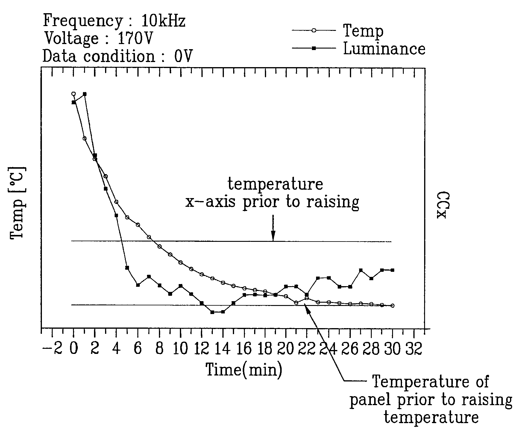
[0073]As described above, the residual image on the PDP is generated by the heating of the phosphors due to a high temperature and a high voltage

[0074]In the present invention, the residual image phenomenon is reviewed with a variation in the power. The variation in the power, e.g., the impedance has an electrical resistance component, and thus, if the discharge area is changed, the impedance is normally changed, too.

[0075]The reasons for the PDP residual image phenomenon can be summarized roughly as two reasons. The first is the one generated due to the luminance difference. ...


PUM


Abstract

A cooling apparatus of a plasma display panel and a method for stabilizing the PDP to minimize the residual image on the display are disclosed. In particular, the present invention minimizes the residual image that is generated due to the degeneration of phosphors caused by a high voltage and a high temperature.

Description

[0001]This application claims the benefit of the Korean Application No. P2001-75612 filed on Dec. 1, 2002 which is hereby incorporated by reference.BACKGROUND OF THE INVENTION[0002]1. Field of the Invention[0003]The present invention relates to a plasma display panel, and more particularly, to a cooling apparatus of a plasma display panel (PDP) and a method for stabilizing the PDP by minimizing the residual image on the display.[0004]2. Discussion of the Related Art[0005]Generally, a plasma display panel (PDP) has many advantages suitable for the enlargement of various flat board types of display devices.[0006]Due to the above and other reasons, the PTP has drawn a lot of attention to enlargement of the panel size.[0007]As shown in FIG. 1, the most typical form of the PTP is the one that includes three-electrode and is driven by AC voltage, which is referred to as an AC surface discharge type PTP.[0008]FIG. 1 is a perspective view of the discharge cell structure of a general 3-elect...

Claims


Application Information

Patent Timeline
Patent Type & Authority Patents(United States)
IPC IPC(8): G09G3/10G09G3/28G09F9/00G09G3/20H04N5/64G09G3/288G09G3/291G09G3/294G09G3/296G09G3/298H01J17/28H05K7/20
CPCG09G3/28H05K7/20972G09G2320/0257G09G2330/045H01J2217/492G09G2320/041G09G2300/0426G09G3/298H01J17/28
Inventor RHEE, BYUNG JOON
Owner LG ELECTRONICS INC
Why Eureka
Try Eureka