Cleaning system

a cleaning system and cleaning technology, applied in the direction of carpet cleaners, cleaning equipment, printing, etc., can solve the problems of brush drippage, difficult to use these devices to clean corners around bathtubs, and narrow grooves between wall tiles, etc., to achieve convenient cleaning, convenient affixed to the handle, and convenient cleaning

Active Publication Date: 2009-11-03
SC JOHNSON & SON INC
View PDF32 Cites 35 Cited by
  • Summary
  • Abstract
  • Description
  • Claims
  • Application Information

AI Technical Summary

Benefits of technology

[0017]In another preferred aspect an absorption capacity of the interior layer prior to impregnation with the formula can be over 500% of its starting weight, and the impregnating formula occupies less than 50 percent of the absorption capacity of the interior layer. Hence, a large amount of impregnating formula can be held in the pad (thereby extending the life of the pad), yet there is enough spare absorption capacity to facilitate pick-up of water so as to efficiently dilute the concentrate during use.
[0018]In still other preferred aspects the lower layer is formed of a layer of air filter media. This provides an inherent abrasive characteristic, yet passes air in a manner that induces foaming. Another preferred structure is to include polyethylene film linked to a lower side of the upper layer (above the interior layer) to enhance the structural integrity of the upper layer.
[0024]It is most preferred for the outer layers to have very low absorption capacity while the middle / interior layer that is impregnated has a higher absorption capacity. This allows the middle layer to retain water when the consumer initially wets the pad, allows the water to mix with the concentrated formula in a controlled manner, and improves foaming characteristics. An absorption capacity for the middle layer of over 500% of its starting weight (preferably over 1000%; even more preferably about 1300%) is preferred.
[0025]From a functional standpoint the top layer provides a loop-type attachment system. The middle layer holds the concentrate cleaning fluid, while also providing an empty reservoir to receive water when the pad is wetted (to facilitate foaming and reduce the need for rewetting). The lower layer is a loose abrasive material that performs a scrubbing function, while also aerating the chemical to enhance foaming.
[0027]Particularly desirable pads of the present invention can deliver an essentially constant concentration of cleaning or other surface treating liquid when wetted repetitively up to at least three times. Such pads will also have a middle layer that wicks material from the center of the pad to its periphery quite slowly, thereby facilitating enclosure of the middle layer before impregnation liquid has wicked to its radial periphery.
[0028]The present invention thus provides cleaning pads, a handle and a container that can be manufactured inexpensively. The pads can be easily affixed to the handle for use, without the consumer needing to contact the pad. Both can be housed in a compact container for shipping and storage. The assembled handle and pad are particularly efficient at cleaning tight corners and narrow grooves between tiles.

Problems solved by technology

This can make it difficult to use these devices to clean corners around bathtubs, or to clean narrow grooves between wall tiles.
However, they become dirty and / or smelly over time.
Further, such brushes drip after use.
Thus, consumers dislike storing them between uses.
However, the cleaning heads and / or the handles used therewith were unduly expensive given the comparative cost to using a permanent structure type scrub brush.
Further, they had no optimal storage system for the handle and replacement pads between usage.
However, that container did not provide a separate housing for the handle before use, nor did the container house replaceable cleaning elements.
However, that patent did not suggest that such a well could be used for holding a handle (as opposed to providing a structure compatible with another nested container).
However, there was no discussion in this patent of using such formulations with multi-layer pads, or with such pads linked to handles.
However, that application did not disclose impregnation of an interior layer of the pad with a cleaning liquid, or disclose optimized layer materials.
In sum, the art did not provide optimized handles, optimized replaceable pads, or an optimized container system, for a scrubbing / surface treating device having a replaceable contact element.

Method used


Image

  • Cleaning system
  • Cleaning system
  • Cleaning system

Examples


Embodiment Construction

[0047]A. Overview

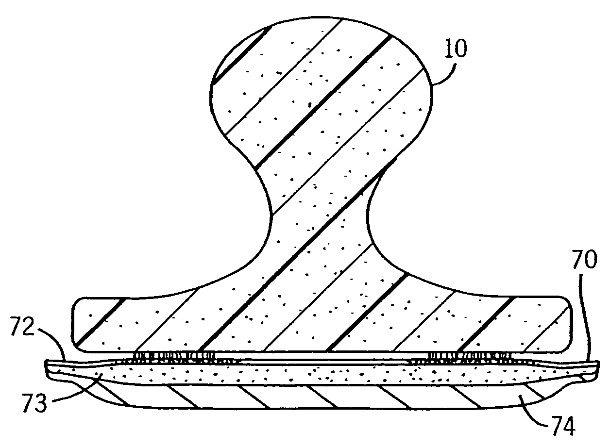
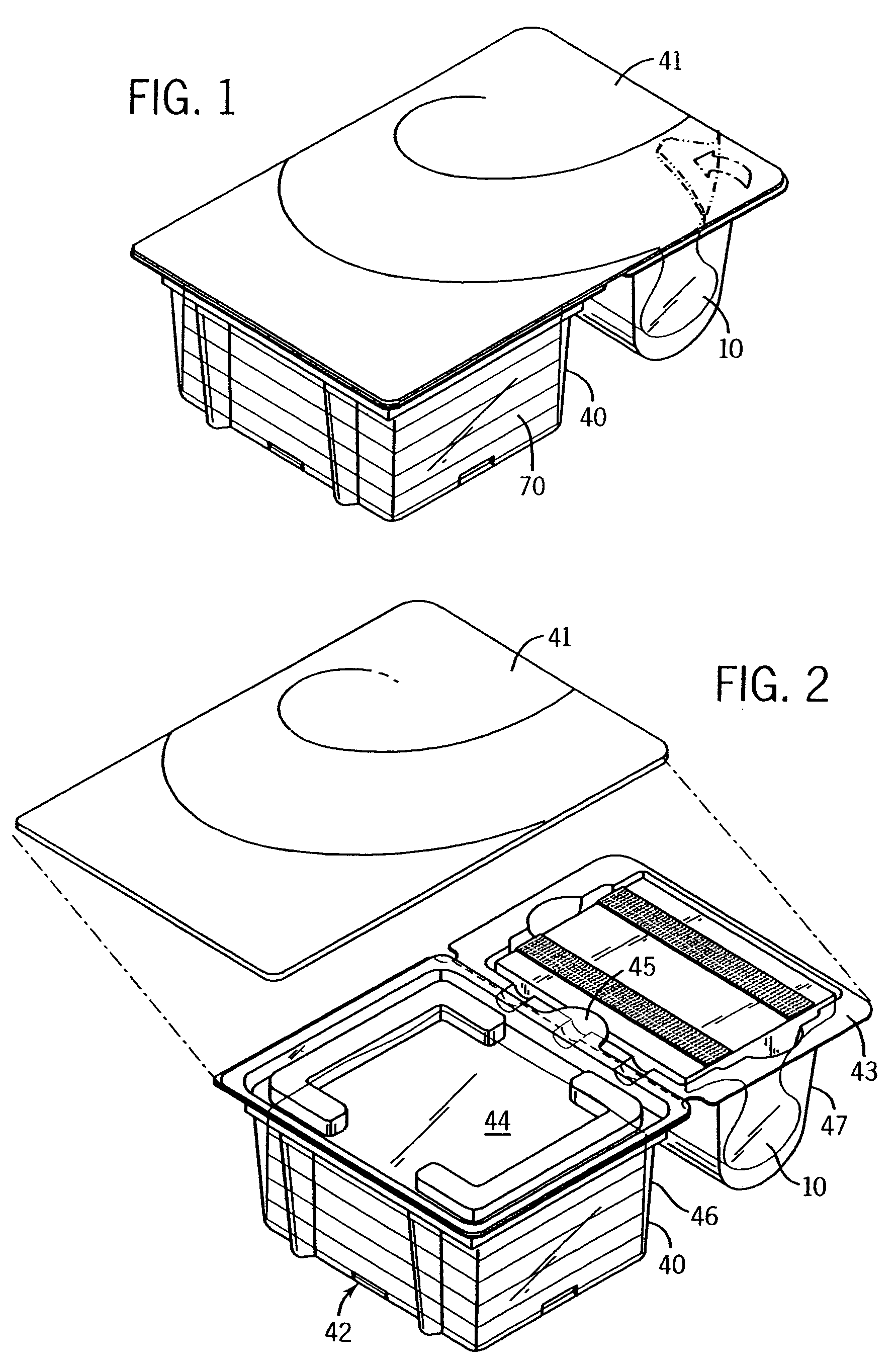
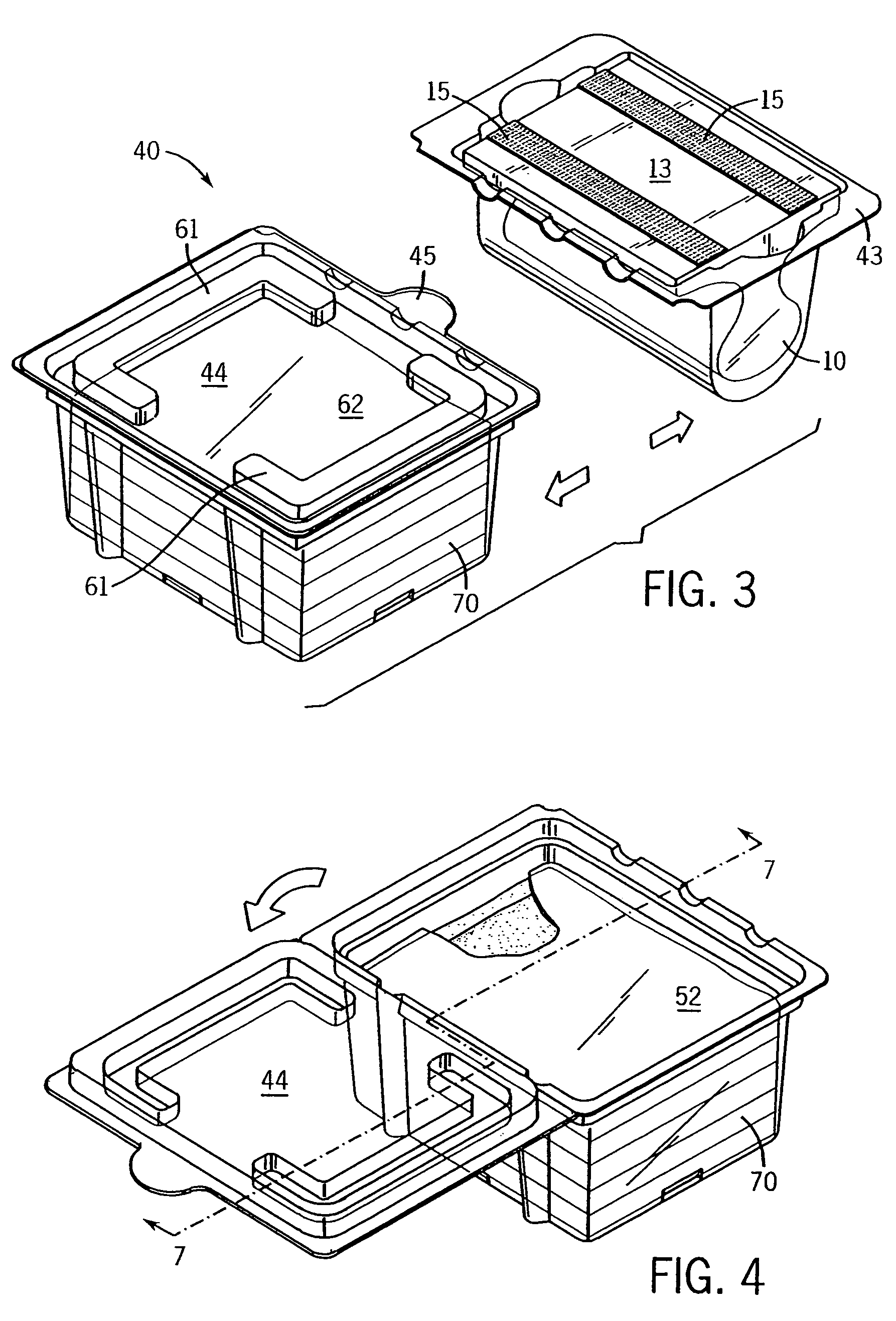
[0048]The preferred cleaning system is depicted in the enclosed drawings. As shown in FIGS. 1 and 2, the system has a handle 10, a container 40, and a plurality of multi-layer cleaning pads 70. These features will be described below.

[0049]B. The Handle

[0050]The handle 10 is almost entirely an extruded body, such as an extruded foam body, most preferably an extruded polyethylene foam body such as a Nomaco polyethylene foam body. The foam can be extruded in a continuous strip having the FIG. 12 profile, then cut into lengths of about 8-16 centimeters, (preferably about 11.5 centimeters). A most preferred foam has a density of between 15 and 35 kilograms / meter3 (preferably a density of about 24 kilograms / meter3).

[0051]Because it is extruded, the handle will have a cross section that is uniform throughout its length (except perhaps at the very ends if the cutting is not straight). Because it can be truncated by simple cutting, it is inexpensive to produce. Surprisingly,...


PUM

PropertyMeasurementUnit
lengthsaaaaaaaaaa
lengthsaaaaaaaaaa
densityaaaaaaaaaa

Abstract

Disclosed are hand-held scrubbing devices of the type having a replaceable pad. These devices have a handle which is extruded and extremely flexible. The pads are multi-layer and may be pre-impregnated with a cleaner concentrate. A shipping / docking container for use therewith is also disclosed which has the capability of reducing its overall size once the product has reached the consumer.

Description

CROSS-REFERENCE TO RELATED APPLICATIONS[0001]This application claims priority based on U.S. provisional application 60 / 606,951, which was filed on Sep. 3, 2004.STATEMENT REGARDING FEDERALLY SPONSORED RESEARCH / DEVELOPMENT[0002]Not applicableBACKGROUND OF THE INVENTION[0003]The present invention relates to cleaning and other surface treating devices that have a permanent or semi-permanent handle and a replaceable cleaning / surface treating element. More particularly, it relates to such devices that are configured for use in a manner similar to a scrub brush, and to containers useful for shipping, displaying, and storing them.[0004]A variety of cleaning / surface treating devices are known in which a handle removably links to a replaceable cleaning / surface treating element. This is often seen in connection with floor mops having replaceable sponge-like or rag-like heads. Most of these devices attach the replaceable elements to the handle with some form of articulatable joint, and in any e...

Claims


Application Information

Patent Timeline
Patent Type & Authority Patents(United States)
IPC IPC(8): B08B1/00
CPCA47L17/08A47L13/17
Inventor MORGAN, TERRA J.STURDY, KARA E.MOODYCLIFFE, OLIVIA M.
Owner SC JOHNSON & SON INC
Why Eureka
Try Eureka