Systems and methods for improving performance in a digital amplifier by adding an ultrasonic signal to an input audio signal

a technology of ultrasonic signal and digital amplifier, which is applied in the field of electronic devices, can solve problems such as coincidence distortion, achieve the effects of reducing noise, reducing noise, and improving the performance of switching amplifiers

Inactive Publication Date: 2010-01-19
INTERSIL INC
View PDF13 Cites 77 Cited by
  • Summary
  • Abstract
  • Description
  • Claims
  • Application Information

AI Technical Summary

Benefits of technology

[0008]This disclosure is directed to systems and methods for improving the performance of switching amplifiers that solve one or more of the problems discussed above. In one particular embodiment, an ultrasonic signal (e.g., a tone at half of the switching frequency, Fswitch) is introduced into an audio signal received by a switching amplifier. The added ultrasonic signal shifts the signals (A, B) that are input to power switches in the amplifier so that they do not switch nearly simultaneously, and it causes the output current to be well defined to eliminate dead time distortion at low signal levels. Adding the ultrasonic signal causes the distortion to shift to an amplitude greater than zero. Signals that exceed this amplitude will experience the distortion, but the distortion will be less noticeable than in lower-amplitude signals. Signals that do not exceed this amplitude will not experience the distortion at all. While the same effect can also be achieved by skewing signals A and B with respect to each other (i.e., adjusting the relative timing of the signals,) adding a signal is simpler, easier to implement, and equally effective. Another benefit of adding an ultrasonic signal is to draw switching energy away from the switch frequency and its harmonics. This can be used to avoid potential problems of interference with AM radio reception.
[0012]Another embodiment comprises a method implemented in a switching amplifier that amplifies an audio signal. This method includes generating an ultrasonic signal and adding the ultrasonic signal to the audio signal prior to amplifying it. The method may reduce coincidence distortion at low signal levels within the amplifier, reduce dead time distortion within the amplifier, and / or reduce radiation of a signal in an AM radio band. The ultrasonic signal may, in one embodiment, comprise a tone having a frequency which is half the switching frequency of the switching amplifier. The method may include storing a gain coefficient in a programmable memory and multiplying the ultrasonic signal by the gain coefficient. The method may also include multiplying the ultrasonic signal by a nonlinear function of the audio signal. The method may further include reducing a probability of overload in the amplifier by causing the nonlinear function to decrease when the audio signal is large. In one embodiment, the method includes monitoring the operation of the amplifier to detect a clipping- or overload-related condition and adjusting the ultrasonic signal in response to the condition being detected. The detected conditions may include actual or incipient clipping, or actual or incipient overload. In one embodiment, the method is implemented in an amplifier including a noise-shaped quantizer. In this embodiment, the method may include reducing an audio-frequency intermodulation product between the ultrasonic signal and noise produced by the quantizer by configuring the noise transfer function of the quantizer to have a reduced amplitude at frequencies close to the frequency of the ultrasonic signal.

Problems solved by technology

Coincidence distortion is caused because, at low signal levels, the two sides of the bridge switch almost simultaneously.

Method used


Image

  • Systems and methods for improving performance in a digital amplifier by adding an ultrasonic signal to an input audio signal
  • Systems and methods for improving performance in a digital amplifier by adding an ultrasonic signal to an input audio signal
  • Systems and methods for improving performance in a digital amplifier by adding an ultrasonic signal to an input audio signal

Examples


Embodiment Construction

[0033]One or more embodiments of the invention are described below. It should be noted that these and any other embodiments described below are exemplary and are intended to be illustrative of the invention rather than limiting.

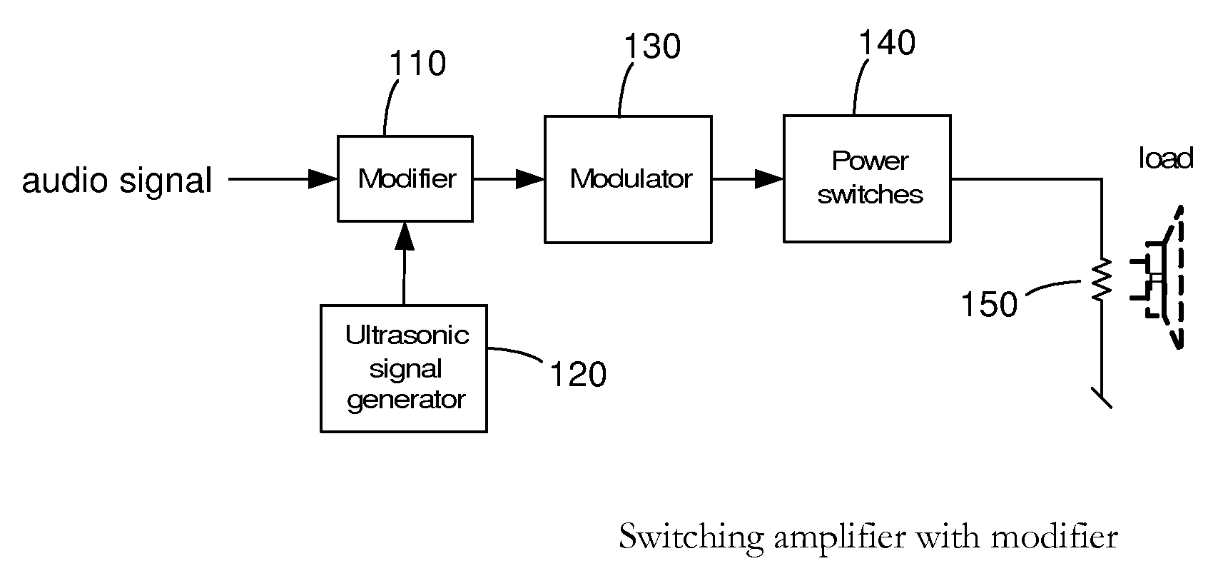
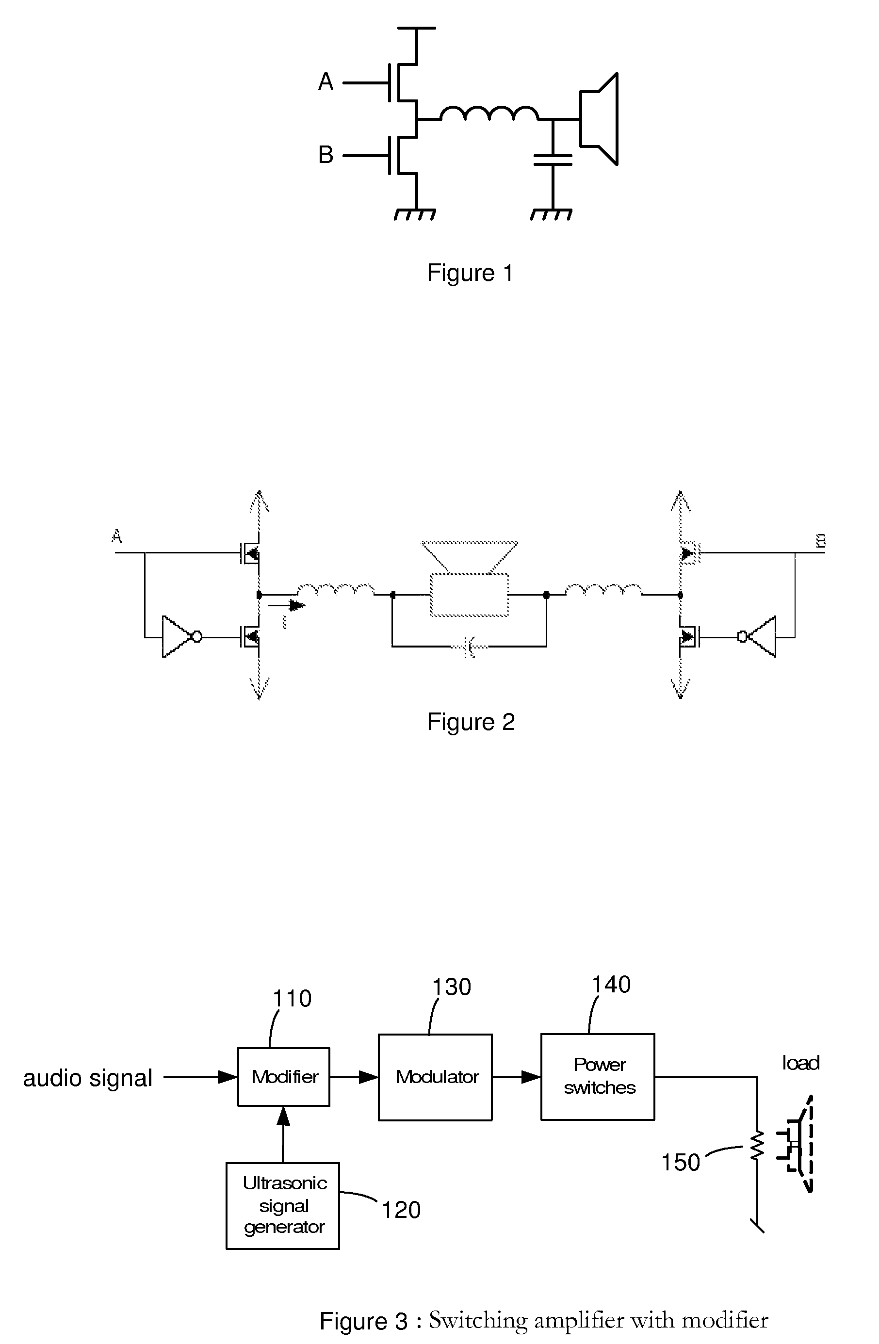
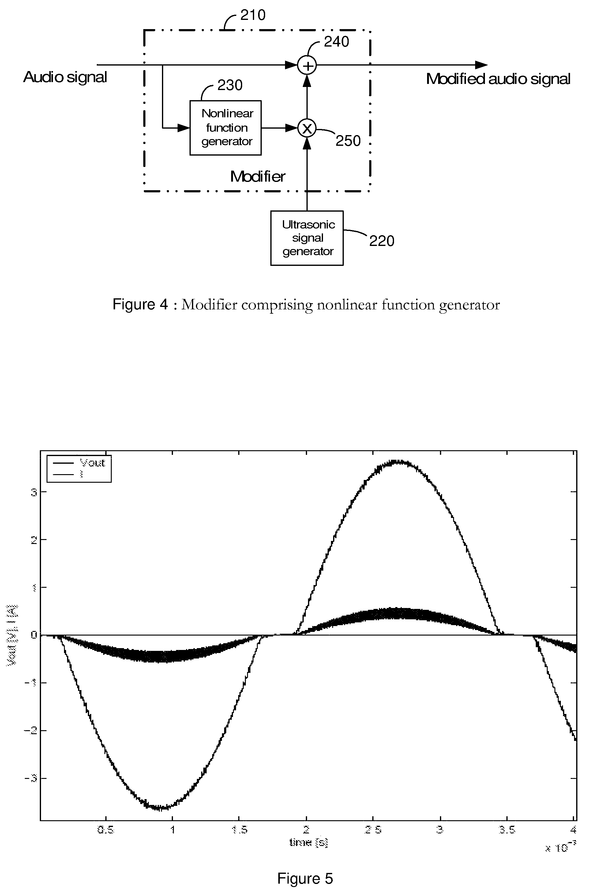
[0034]As described herein, various embodiments of the invention comprise systems and methods in which a tone (e.g., at half of the switching frequency, Fswitch) is introduced into the audio signal of a switching amplifier. The added tone shifts the signals (A, B) input to the power switches so that they do not switch nearly simultaneously, and it causes the output current to be well defined to eliminate dead time distortion at low signal levels. Adding the tone at Fswitch / 2 causes the distortion to shift to an amplitude greater than zero. Signals that exceed this amplitude will experience the distortion, but the distortion will be less noticeable than in lower-amplitude signals. Signals that do not exceed this amplitude will not experience the distortion at a...


PUM


Abstract

Systems and methods in which an ultrasonic signal is introduced into an audio signal before the audio signal is amplified by a switching amplifier. The added ultrasonic signal (e.g., a tone at half the amplifier's switching frequency) shifts the signals input to a set of power switches so that they do not switch nearly simultaneously. The ultrasonic signal causes the output current to be well defined to eliminate dead time distortion at low signal levels. Adding the tone ultrasonic signal causes the distortion to shift to an amplitude greater than zero. Signals that exceed this amplitude will experience the distortion, but the distortion will be less noticeable than in lower-amplitude signals. Signals that do not exceed this amplitude will not experience the distortion at all. Adding an ultrasonic signal may also draw energy away from the switch frequency and its harmonics to interference with AM radio reception.

Description

CROSS-REFERENCE TO RELATED APPLICATIONS[0001]This application claims the benefit of U.S. Provisional Patent Application 60 / 761,614, filed Jan. 24, 2006, which is incorporated by reference as if set forth herein in its entirety.BACKGROUND[0002]1. Field of the Invention[0003]The invention relates generally to electronic devices, and more particularly to systems and methods for improving the performance of switching amplifiers by adding an ultrasonic signal to an input audio signal before amplifying the audio signal.[0004]2. Related Art[0005]Pulse-width modulation (PWM) amplifiers are sometimes used to amplify audio signals. In a two-level PWM modulation scheme, a pair of signals (A, B) are used to switch a pair of FETs on and off to thereby pull the voltage across the load (speaker) alternately up or down. (See FIG. 1.) The signals A and B each consist of a series of pulses of varying widths. If the audio signal is increasing, the high-side signal (A) will have wider pulses and the lo...

Claims


Application Information

Patent Timeline
Patent Type & Authority Patents(United States)
IPC IPC(8): H03F3/38
CPCH03F1/3264H03F3/217H03F3/2173H03F2200/03H03F2200/114H03F2200/351H03F2201/3236H03K17/162H03K17/6871
Inventor ANDERSEN, JACK B.CRAVEN, PETER G.
Owner INTERSIL INC
Why Eureka
Try Eureka