Circuit board with improved ground plane

a ground plane and circuit board technology, applied in the field of circuit boards, can solve problems affecting the signal quality of the circuit board, and achieve the effects of reducing the differences in the impedance of the signal traces, minimizing interaction, and improving signal quality

Inactive Publication Date: 2010-02-16
GOLD CHARM LTD
View PDF9 Cites 6 Cited by
  • Summary
  • Abstract
  • Description
  • Claims
  • Application Information

AI Technical Summary

Benefits of technology

[0006]A circuit board is provided for improving signal quality, including a signal plane for a plurality of signal traces arranged thereon and a ground plane formed by a plurality of tiles connected to each other in an array. Each tile is formed by ground traces. Different line segments of a signal trace mapped on the ground plane cross ground traces of the tiles at similar angles, thereby minimizing interaction between the ground traces and the signal traces to reduce differences in impedances of the signal traces.

Problems solved by technology

That may affect the signal quality of the circuit board.

Method used


Image

  • Circuit board with improved ground plane
  • Circuit board with improved ground plane
  • Circuit board with improved ground plane

Examples


first embodiment

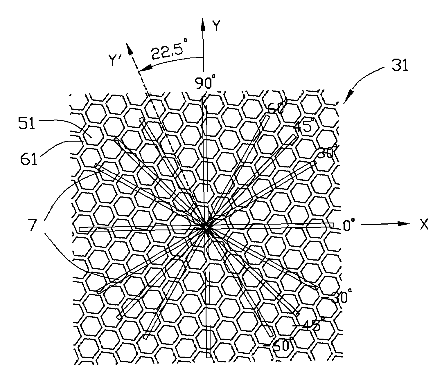
[0020]Referring to FIG. 5, a ground plane 31 in accordance with the present invention is shown. The ground plane 31 includes a plurality of same-sized tiles 51 connected to each other in an array. Each tile 51 is a polygon delimited by six equal straight ground traces 61 connected consecutively end-to-end, forming an equilateral hexagon-shaped tile. The ground plane 31 defines an X-axis along which a straight line segment of a signal trace 7 is arranged. A Y-axis of the ground plane 31 is perpendicular to the X-axis. A straight line passing through one straight ground trace 61 of each tile 51 is designated as a Y′-axis of the tile 51. In the present embodiment, The Y′-axis of each tile 51 is rotated 22.5 degrees relative to the Y-axis of the ground plane 31. Thus, the ground traces 61 are oriented on the ground plane 31 at angles of 22.5, 52.5, 67.5, 112.5, −7.5, −22.5, or −37.5 degrees relative to the X-axis of the ground plane 31. Each straight line segment of the signal traces 7 ...

fourth embodiment

[0024]Referring to FIG. 8, which shows a ground plane 34 of a circuit board in accordance with a In this embodiment, the ground plane 34 includes a plurality of same-sized and generally triangle-shaped tiles 54 with rounded convex corners and rounded concave sides. Each tile 54 is formed by curved ground traces 64.

fifth embodiment

[0025]Referring to FIG. 9, which shows a ground plane 35 of a circuit board in accordance with a In this embodiment, the ground plane 35 includes a plurality of same-sized and generally square-shaped tiles 55 with wavy sides. Each tile 55 is formed by curved ground traces 65.


PUM


Abstract

A circuit board is provided for improving signal quality, including a signal plane for a plurality of signal traces arranged thereon and a ground plane formed by a plurality of tiles connected to each other in an array. Each tile is formed by ground traces. Different line segments of a signal trace mapped on the ground plane cross ground traces of the tiles at similar angles, thereby minimizing interaction between the ground traces and the signal traces to reduce differences in impedances of the signal traces.

Description

BACKGROUND OF THE INVENTION[0001]1. Field of the Invention[0002]The present invention relates to a circuit board, particularly to a circuit board with an improved ground plane.[0003]2. Description of Related Art[0004]Circuit boards such as printed circuit boards (PCBs) are widely used in conventional electronic devices. In designing a contemporary PCB, controlling trace impedance is very important. The impedance relates to a number of parameters, such as the widths and distances of signal traces, and the thicknesses of media layers of the PCB. For example, a circuit board includes a signal plane for signal traces arranged thereon and a ground plane for ground traces arranged thereon. A media layer is disposed between the signal plane and the ground plane. Generally, the thickness of the media layer is so thin, that the impedance of the signal traces is reduced too much. That may affect the signal quality of the circuit board.[0005]What is needed, therefore, is a circuit board having...

Claims


Application Information

Patent Timeline
Patent Type & Authority Patents(United States)
IPC IPC(8): H05K1/03
CPCH05K1/0253H05K1/0224H05K2201/09681
Inventor LIN, YU-HSUWU, JENG-DACHAO, CHIH-HANG
Owner GOLD CHARM LTD
Why Eureka
Try Eureka