Shield box

a shielding box and shielding technology, applied in the field of shield boxes, can solve the problems of reducing the shielding performance prone to movement weakening of the shielding wire, so as to improve the shielding reliability, improve the shielding performance, and improve the resistance to vibration

Inactive Publication Date: 2010-02-16
YAZAKI CORP
View PDF12 Cites 7 Cited by
  • Summary
  • Abstract
  • Description
  • Claims
  • Application Information

AI Technical Summary

Benefits of technology

[0009]The present invention has been made in consideration for the above-described circumstances. It is an object of the present invention to provide a shield box that houses therein the plurality of shield connectors interconnecting the shield wires, wherein each of all the shield connectors can be surely fixed to the shield box concerned, whereby the shielding reliability can be achieved.
[0021]Furthermore, even when the attachment bracket of the upper box is composed by bending the side plate thereof, the bead is provided on the plate surface of such a bent portion, whereby flexural rigidity of the attachment bracket concerned can be enhanced, and the shielding performance in a state where the shield connectors are fixed can be stabilized.

Problems solved by technology

Hence, the shield wires are prone to move.
Moreover, when the wires undesirably move, there is an apprehension that shield performance thereof may be decreased.
In particular, when three or more of the shield wires are arrayed, if center portions of the sandwiching members sag and warp, then restraint on the center shield wire becomes prone to be weak, and the respective wires become prone to move.
Hence, in this case, there is a problem that shielding property is decreased.
A similar problem occurs also in the case of arraying and housing a plurality of shield connectors, which interconnect the shield wires, in an inside of a shield box.
However, unless the shield box and the shield terminals are surely brought into contact with and conducted to each other, then there is a possibility that the shielding reliability may be impaired.

Method used


Image

  • Shield box
  • Shield box
  • Shield box

Examples


Embodiment Construction

[0038]A description will be made blow of an embodiment of the present invention while referring to the drawings.

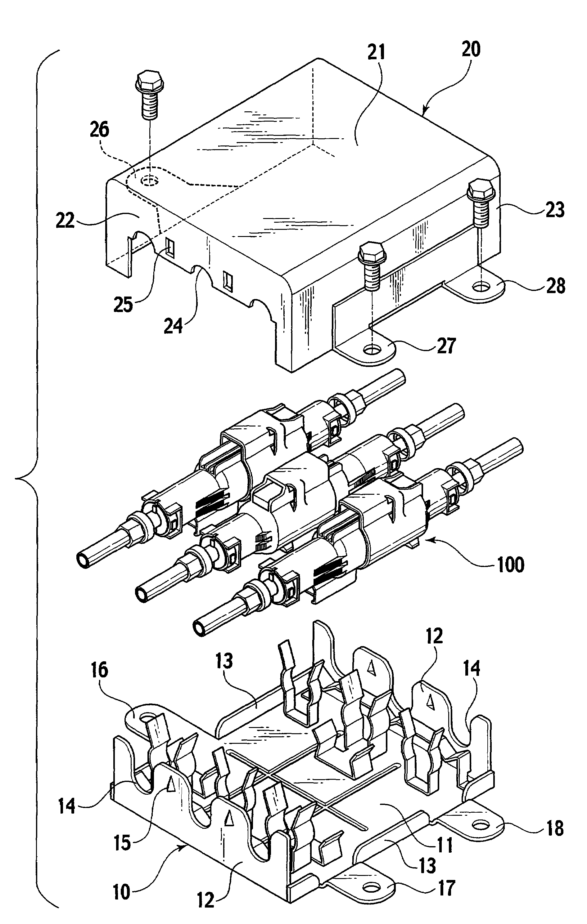
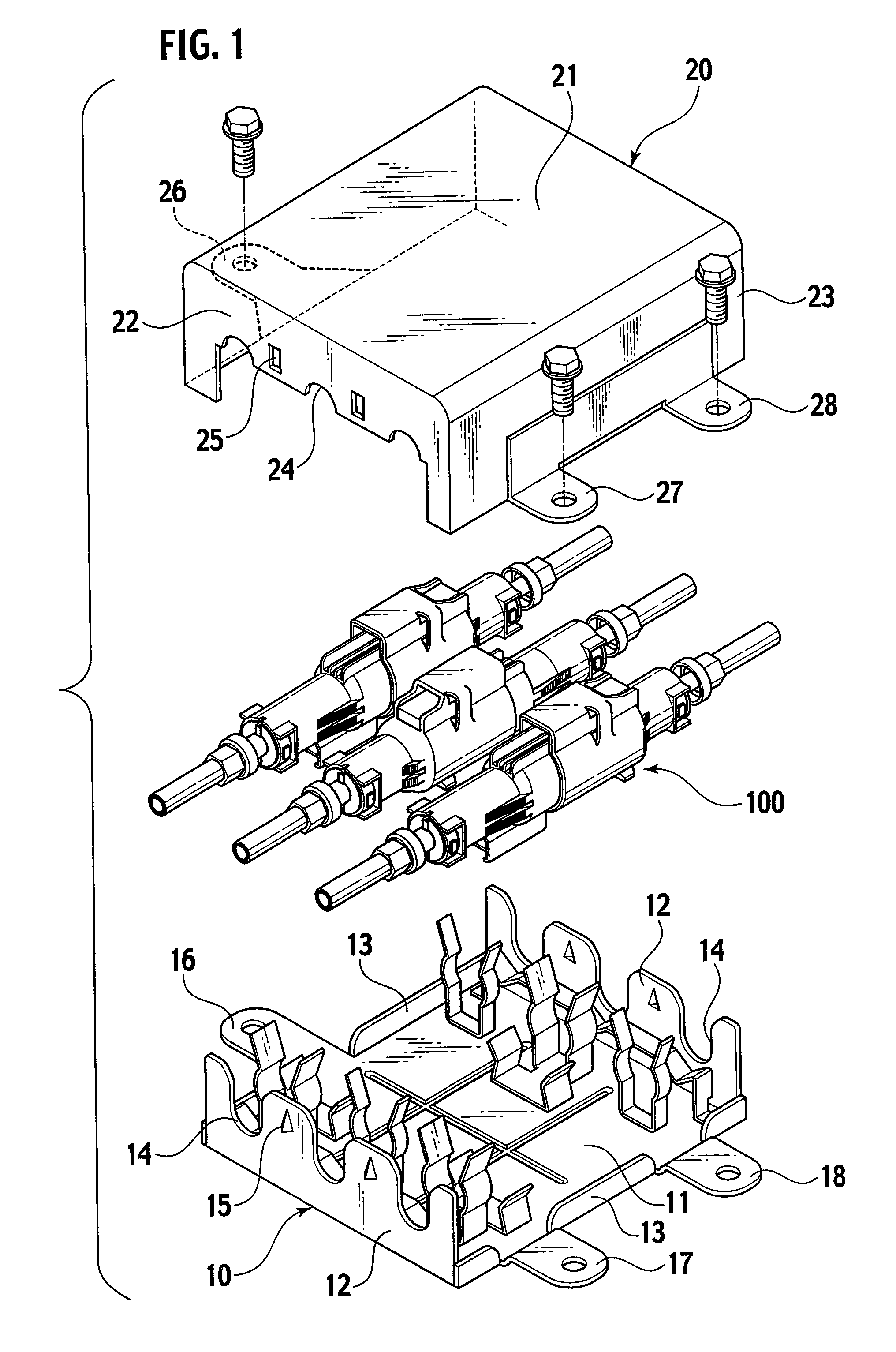
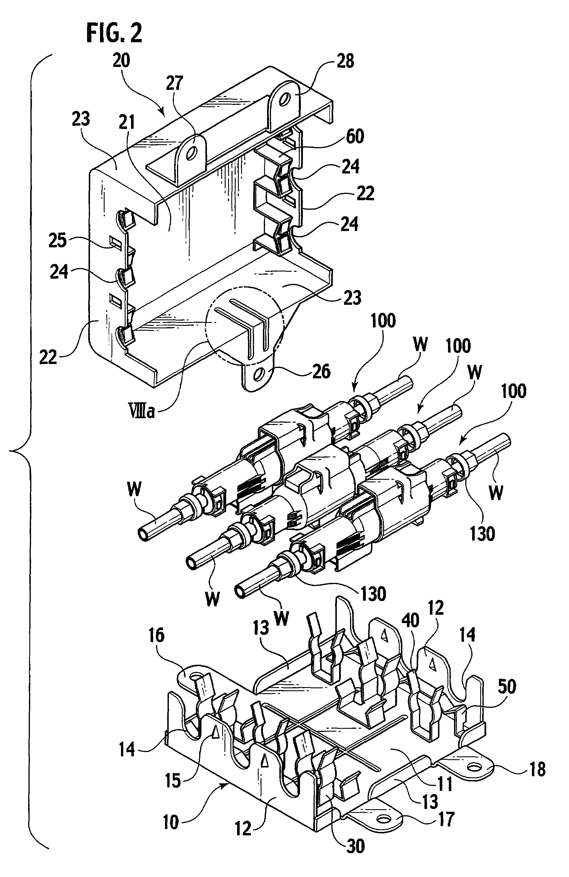
[0039]As shown in FIG. 1 and FIG. 2, a shield box is composed of an upper box 20 and a lower box 10, which are made of metal and are combined with each other. The shield box houses therein three shield connectors 100, each of which interconnects shield wires W, and electromagnetically shields the entirety of the shield connectors 100 and the shield wires W. Moreover, as shown in FIG. 12, the shield box is electrically connected to shield conductors (braids) Ws of the respective shield wires W, and grounds shield terminal portions 130 exposed to both ends of the respective shield connectors 100.

[0040]As shown in FIGS. 3 to 5C, the lower box 10 includes: a lower surface plate 11; fore-and-aft end surface plates 12; left-and-right side surface ribs 13; and attachment brackets 16, 17 and 18 protruded outward on left-and-right side edges of the lower surface plate 11.

[0041]Mean...


PUM


Abstract

A shield box is composed of metal-made upper box and lower box, which are combined with each other. The shield box houses therein a plurality of shield connectors interconnecting shield wires, and thereby electromagnetically shields entirety of the shield connectors and the shield wires. On an upper surface of a lower surface plate of the lower box, clamp fittings capable of restraining the respective shield connectors in axial, axial rotation, left-and-right and up-and-down directions thereof are provided. On opposite surfaces of the upper and lower boxes, press fittings are provided to sandwich shield terminal portions from upper and lower sides and conduct the shield terminal portions to the upper and lower boxes when the upper and lower boxes are matched with each other. The shield terminal portions, which are electrically connected to shield conductors of respective shield wires and are exposed to both ends of the respective shield connectors, are grounded.

Description

CROSS REFERENCE TO RELATED APPLICATION[0001]This application claims benefit of priority under 35 USC 119 based on Japanese Patent Application P2007-191965 filed Jul. 24, 2007, the entire contents of which are incorporated by reference herein.BACKGROUND OF THE INVENTION[0002]1. Field of the Invention[0003]The present invention relates to a shield box capable of surely fixing all shield connectors thereto, and capable of enhancing shielding reliability thereof.[0004]2. Description of the Related Art[0005]Japanese Patent Laid-Open Publication No. 2002-216907 discloses a structure of grounding shield terminals, which are conducted to shield conductors of a plurality of shield wires, to a ground member while arraying and fixing terminals of the respective wires.[0006]In accordance with such a shield structure, the plurality of shield wires are arrayed in parallel to one another between two (first and second) conductive sandwiching members, and the plurality of shield wires are sandwiched...

Claims


Application Information

Patent Timeline
Patent Type & Authority Patents(United States)
IPC IPC(8): H01R13/648H05K9/00
CPCH01R13/6589H01R13/6593H01R9/226H01R13/516
Inventor CHEN, HAIJUNMATSUMOTO, MITSUHIRO
Owner YAZAKI CORP
Why Eureka
Try Eureka