Projector having polarization conversion element array and light shielding sections provided thereon

a technology of polarization conversion elements and arrays, which is applied in the field of projectors, can solve the problems of degrading the efficiency of cooling the polarization conversion element, increasing the component cost and assembly cost of the projection video apparatus, and increasing the cost of assembling, so as to improve the viewing angle characteristics of the entrance side polarization plate, improve the light intensity ratio of red light, and reduce the color temperature of the light beam

Active Publication Date: 2012-05-29
SEIKO EPSON CORP
View PDF12 Cites 6 Cited by
  • Summary
  • Abstract
  • Description
  • Claims
  • Application Information

AI Technical Summary

Benefits of technology

[0011]According to the configuration described above, it becomes suitable for adjusting the contrast of an image displayed of a screen in accordance with, for example, the viewing angle characteristic of the Modulation device, thus the contrast can be improved. In addition, when the first light shielding section is a thin film provided with the opening section and the light shielding section is formed on the entrance surface, the cooling efficiency of the polarization conversion element array can be improved. Further, by forming at least a part of the opening section to reach an end of the entrance surface, in the mask as a jig used for forming the thin film on the entrance surface, the mask member for forming the opening section can be coupled to be formed of a single constituent. Therefore, compared to the case of preparing the mask formed of separate members and forming the thin film with the mask, the formation of the mask on the entrance surface can efficiently be executed, the misalignment of the opening section with respect to the entrance surface can be reduced, and the thin film can be formed with high accuracy.
[0013]In the case in which a part of the area of the opening section is formed to reach the outline of the entrance surface, a part of the area of the opening section formed in the ineffective entrance area may occur in some cases. However, since the part of the area formed in the ineffective entrance area can be shielded by the light shielding member having such a configuration, the light beam can be prevented from entering the area formed in the ineffective entrance area of the opening section formed on the entrance surface.
[0015]According to the configuration described above, since the thin film light shielding section formed on the entrance surface is formed of the metallic thin film, in the case of forming the light shielding section, for example, of an aluminum thin film, the incident light beam can reliably be shielded. Further, since the thin film is made of metal, the thin film has good thermal conductivity, and it is also possible to improve the cooling efficiency of the polarization conversion element array.
[0019]According to such a configuration as described above, the dielectric multilayer film shields the wavelength band of the green light and the blue light, and transmits the red light. Thus, in the case in which the light beam emitted from the light source is high in the color temperature and appears bluish white, by shielding the green light and the blue light while transmitting the red light, namely by relatively increasing the light intensity ratio of the red light, it becomes possible to lower the color temperature of the light beam emitted from the dielectric multilayer film to adjust the white balance toward a reddish white color.
[0020]An aspect of the invention is directed to the projector of any of the above aspects of the invention, wherein the modulation device preferably includes an entrance side polarization plate to which the linearly polarized light beam is input, a liquid crystal panel adapted to modulate the light beam transmitted through the entrance side polarization plate, and an exit side polarization plate adapted to transmit the light beam modulated by the liquid crystal panel, and the first opening section of the entrance surface is formed so that an F-number relative to an area corresponding to a polarization axis direction of each of the entrance side polarization plate and the exit side polarization plate becomes smaller compared to an F-number relative to an area corresponding to a direction tilted from the polarization axis direction.
[0021]According to such a configuration as described above, by setting the area of the opening section in the polarization axis direction of each of the entrance side polarization plate and the exit side polarization plate to be larger than the area of the opening section in the direction tilted from the polarization axis direction, it is possible to improve the viewing angle characteristics of the entrance side polarization plate and the exit side polarization plate, and further to improve the contrast of the entire image to be projected.

Problems solved by technology

However, if the two light shielding plates, namely the first light shielding plate and the second light shielding plate, are provided as described in the Document 1, the number of components of the light shielding plates is increased, and the sliding structure becomes complicated, which causes a problem of increasing the component cost and the assembling cost of the projection video apparatus.
Further, when cooling the polarization conversion element using a cooling fan, there is a conceivable problem that the use of two light shielding plates causes the cooling air to be blocked, which degrades the efficiency of cooling the polarization conversion element.

Method used


Image

  • Projector having polarization conversion element array and light shielding sections provided thereon
  • Projector having polarization conversion element array and light shielding sections provided thereon
  • Projector having polarization conversion element array and light shielding sections provided thereon

Examples


embodiment

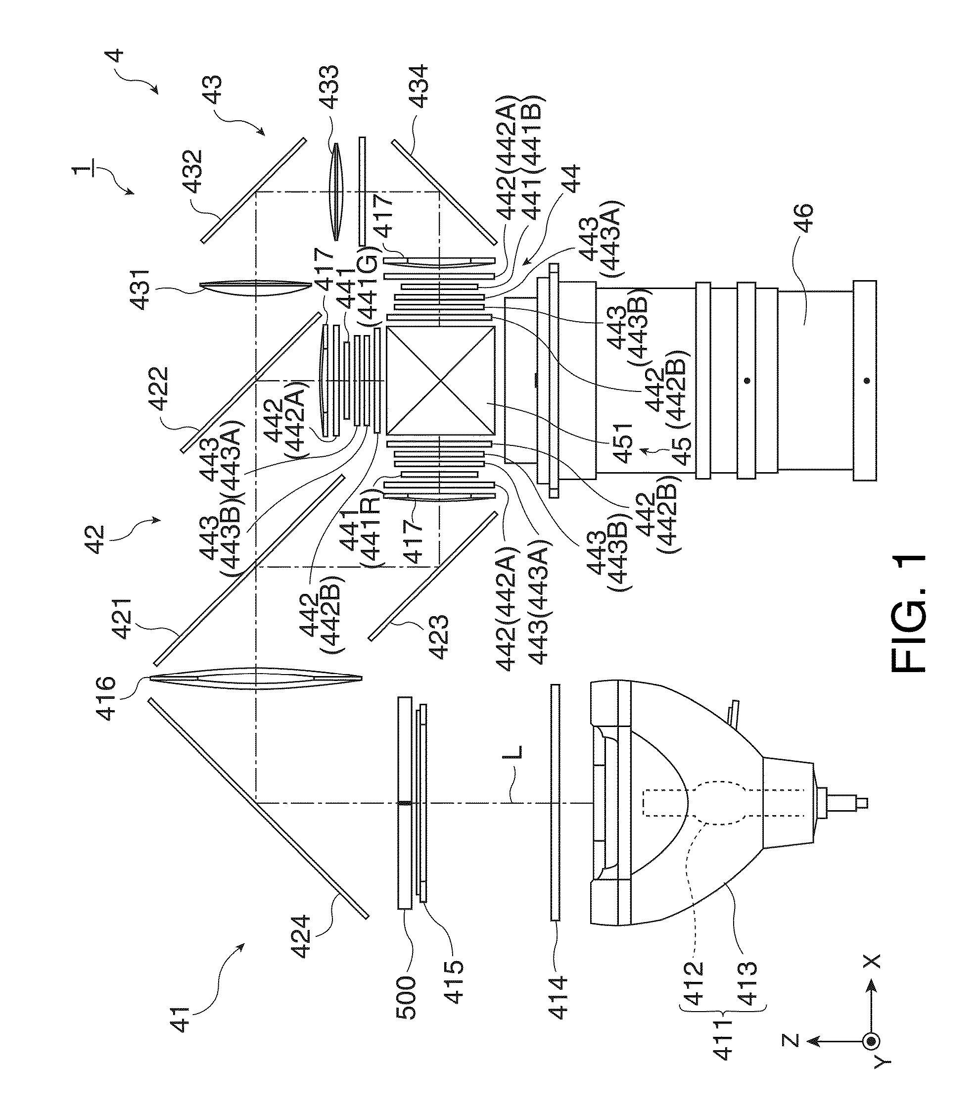
[0034]FIG. 1 is a diagram showing a schematic configuration of an optical system of a projector according to the present embodiment of the invention. A configuration and an operation of the optical system 4 will be explained with reference to FIG. 1.

[0035]The optical system 4 of the projector 1 is provided with an integrator illumination optical system 41 as an illumination optical device, a color separation optical system 42, a relay optical system 43, a modulation device 44, a color combining optical system 45, and a projection lens 46 as a projection device.

[0036]The integrator illumination optical system 41 is an optical system 4 for substantially evenly illuminating the image forming area of the three liquid crystal panels 441 (the liquid crystal panels 441 for respective colored light beams of red light beam, green light beam, and blue light beam are represented as liquid crystal panels 441R, 441G, and 441B, respectively) forming the modulation device 44. The integrator illumi...

modified example 1

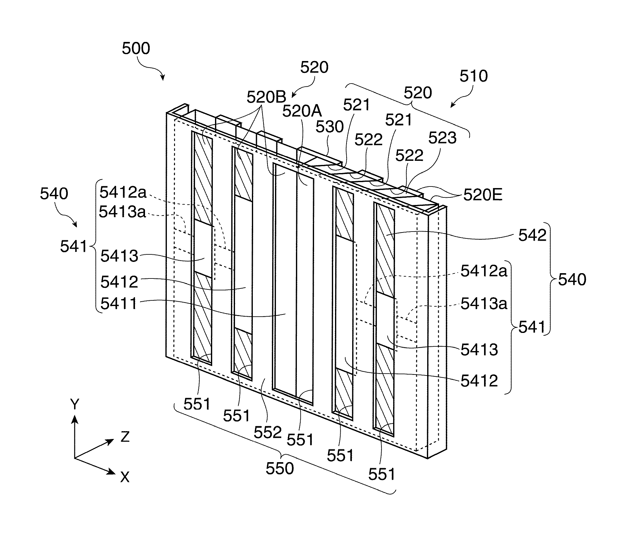
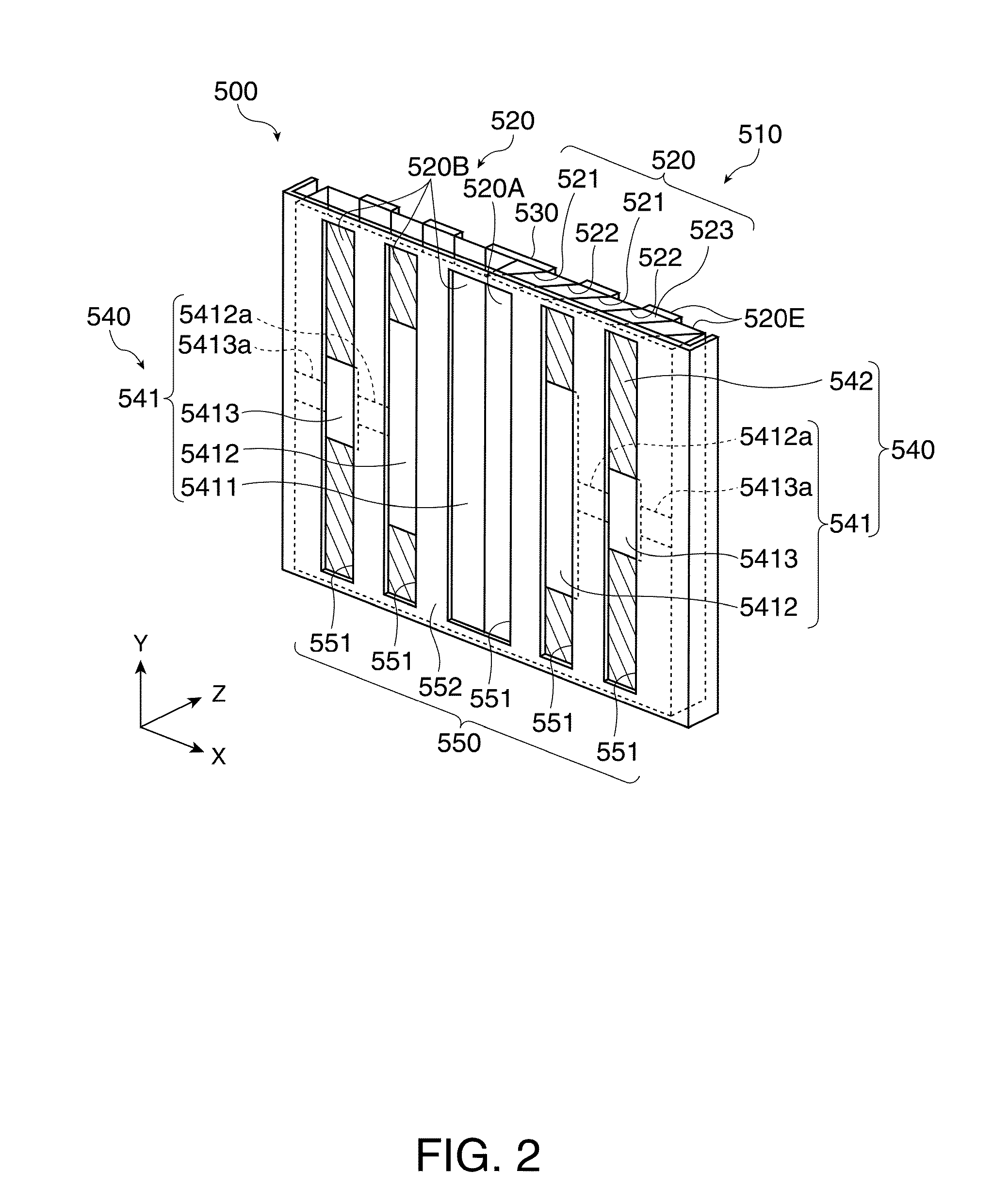
[0099]In the embodiment described above, the light shielding sections 542 of the thin film 540 is formed of a thin film 540 made of metal (aluminum) . However, this is not a limitation, but the light shielding sections of the thin film can also be formed of a dielectric multilayer film for shielding at least a part of the wavelength band in the wavelength band of the incident light beams. The dielectric multilayer film can be formed by executing coating on the entrance surface 520A using the same mask as in the embodiment described above, for example.

[0100]Since the white balance can be adjusted with respect to the color temperature of the light beams (the incident light beams) emitted by the light source 411 by using such a dielectric multilayer film for the light shielding sections of the thin film to shield at least a part of the wavelength band in the wavelength band of the incident light beams, the color balance of the entire image projected on the screen or the like can be adj...

modified example 2

[0103]In the embodiment described above, the areas of the second opening sections 5412 are formed to have a longer vertical size than the areas of the third opening sections 5413. However, this is not a limitation, but it is possible to appropriately set the vertical lengths of the areas of the second opening sections 5412 and the third opening sections 5413 in accordance with the contrast viewing angle characteristic of the polarization plates 442, and further, it is also possible to set the vertical lengths of the areas of the second opening sections 5412 and the third opening sections 5413 to be the same.


PUM


Abstract

A projector includes: a light source; a polarization conversion element array having an entrance surface on which an effective entrance area and an ineffective entrance area are disposed to form stripes; a modulation device adapted to modulate a linearly polarized light beam emitted from the polarization conversion element array in accordance with an image signal; a projection device adapted to project the modulated light beam; a first light shielding section, a part of the entrance surface being provided with the first light shielding section adapted to shield a part of the incident light beam to the effective entrance area; and a first opening section, the first opening section being another area of the entrance surface than the part provided with the first light shielding section, at least a part of the first opening section reaches an end of the entrance surface.

Description

BACKGROUND[0001]1. Technical Field[0002]The present invention relates to a projector.[0003]2. Related Art[0004]Projectors are apparatuses for modulating light beams, which are emitted from light sources, based on image signals to form optical images, and projecting the optical images, thus formed, on projection object surfaces such as screens via projection lenses and so on. In the past, polarization conversion element arrays for converting light beams emitted from light sources into a single type of linearly polarized light beams have been used in projectors for the purpose of improving the efficiency of the emitted light beams. Further, a part of the light beam entering the light beam entrance surface of the polarization conversion element array is input to an effective entrance area of the polarization conversion element array as an incident light beam intended to be input. In contrast, with respect to an ineffective entrance area (i.e., an area to which the incident light beam i...

Claims


Application Information

Patent Timeline
Patent Type & Authority Patents(United States)
IPC IPC(8): G03B21/14G03B21/22G02B5/30G02B27/28
CPCG02B27/1046G02B27/283G03B21/14G03B33/12H04N9/3167G02B5/005G03B21/16G03B21/2073G03B21/208
Inventor HAYASHI, DAISUKEYOSHIDA, KANJI
Owner SEIKO EPSON CORP
Why Eureka
Try Eureka