Thermal treatment system instrument rack and method of selectively thermally treating medical instrument portions

a technology of thermal treatment system and instrument rack, which is applied in the field of thermal treatment system of surgical instruments, can solve the problems of tissue trauma and fogging of scope, and affecting the image quality of the scop

Active Publication Date: 2010-06-01
MICROTEK MEDICAL
View PDF129 Cites 27 Cited by
  • Summary
  • Abstract
  • Description
  • Claims
  • Application Information

AI Technical Summary

Benefits of technology

[0009]Yet another object of the present invention is to maintain the optics of a surgical scope in a dry state by supporting the optics above heated surgical liquid.
[0011]According to the present invention, a system includes a cabinet, a basin positioned within the cabinet to contain and thermally treat a liquid bath, and a rack or tray disposed on the cabinet that supports exposed scope optics above the liquid bath within the basin. The scope optics resides outside of the bath in a dry state, thereby permitting the remaining scope portions within the bath to be thermally treated. This enables accurate temperature warming of the scope to reduce trauma of tissue and retrieval of enhanced images by the scope during a medical procedure. The present invention permits medical personnel or operating room staff to warm scopes in a controlled environment while maintaining scope optics in a dry state.

Problems solved by technology

For example, a scope that is unwarmed prior to being inserted into a patient body may fog due to differences between the body temperature and scope temperature, thereby impeding or distorting the resulting image.
Inserting a hot or cold scope may damage tissue, thereby leading to infections.
However, since the container generally does not provide temperature control for the liquid and / or scopes, the temperature of the scope is not precisely known by medical personnel.
Accordingly, medical personnel may utilize scopes at inadequate temperatures relative to a patient body, thereby potentially causing tissue trauma and fogging of the scope as described above.
A chemical wipe or spray may be used to reduce fogging instead of warming the scopes; however, the chemical may be inadvertently introduced into the patient, thereby causing complications.

Method used


Image

  • Thermal treatment system instrument rack and method of selectively thermally treating medical instrument portions
  • Thermal treatment system instrument rack and method of selectively thermally treating medical instrument portions

Examples


Embodiment Construction

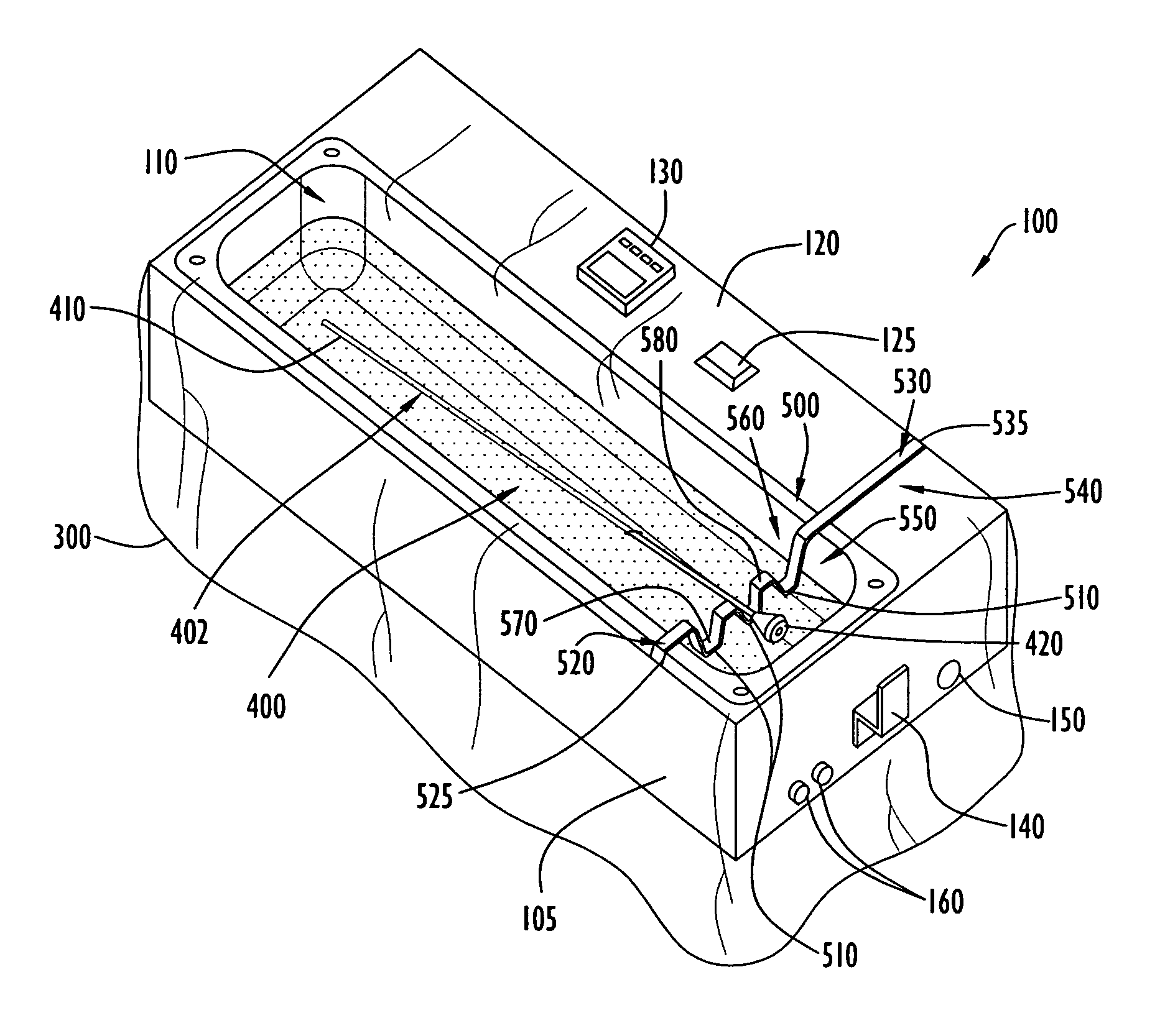
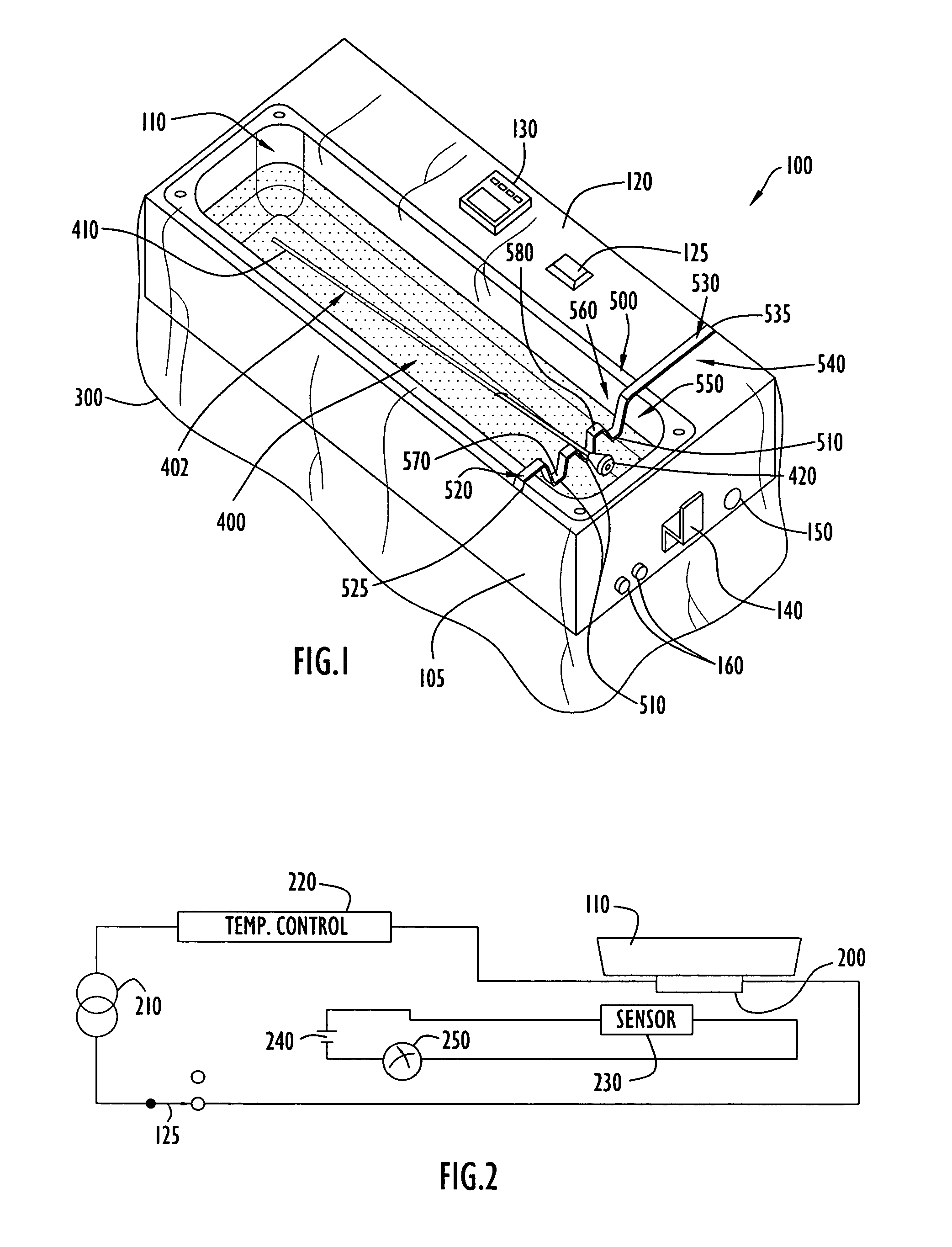
[0015]An exemplary thermal treatment system employing an instrument tray or rack according to the present invention is illustrated in FIG. 1. Specifically, thermal treatment system 100 for thermally treating a sterile medium (e.g., solution or liquid) includes a cabinet or housing 105 in the form of a generally rectangular block and a warming basin 110 recessed into a top surface 120 of cabinet 105. Basin 110 may be of any shape; however, by way of example only, the basin is illustrated as being substantially rectangular. A heater power switch 125 and a temperature controller / indicator 130 are provided on top surface 120 adjacent the warming basin. A support hook 140 is disposed on the cabinet front wall (e.g., as viewed in FIG. 1) and may support a system power cord (not shown). Electrical connections may be made to cabinet 105 via a power port 150 disposed on the cabinet front wall adjacent hook 140. In addition, fuse receptacles 160 may be disposed on the cabinet front wall proxi...


PUM


Abstract

A system according to the present invention includes a cabinet, a basin positioned within the cabinet to contain and thermally treat a liquid bath, and a rack or tray disposed on the cabinet that supports exposed scope optics above the liquid bath within the basin. The scope optics resides outside of the bath in a dry state, thereby permitting the remaining scope portions within the bath to be thermally treated. This enables accurate temperature warming of the scope to reduce trauma of tissue and retrieval of enhanced images by the scope during a medical procedure. The present invention permits medical personnel or operating room staff to warm scopes in a controlled environment while maintaining scope optics in a dry state.

Description

CROSS REFERENCE TO RELATED APPLICATIONS[0001]The present application claims priority from U.S. Provisional Patent Application Ser. No. 60 / 555,327, entitled “Thermal Treatment System Instrument Rack and Method of Selectively Thermally Treating Medical Instrument Portions” and filed Mar. 23, 2004, the disclosure of which is incorporated herein by reference in its entirety.BACKGROUND OF THE INVENTION[0002]1. Technical Field[0003]The present invention pertains to a system for thermally treating surgical instruments. In particular, the present invention pertains to a system for warming surgical scopes in a temperature controlled liquid bath while maintaining optics of the scope in a dry state.[0004]2. Discussion of the Related Art[0005]Surgical scopes (e.g., laparoscopes, endoscopes, arthroscopes, etc.) are used in corrective medical procedures, as well as in medical procedures that image interior viscera such as surfaces of the stomach, small intestines, and colon. The use of surgical s...

Claims


Application Information

Patent Timeline
Patent Type & Authority Patents(United States)
IPC IPC(8): A61B19/10A61F7/00F27D11/00A61B46/23
CPCA61B19/0248A61B2019/0258A61B2019/0249A61B50/10A61B50/22A61B2050/105
Inventor FARIES, JR., DURWARD I.HEYMANN, BRUCE R.HENDRIX, DAVID
Owner MICROTEK MEDICAL
Why Eureka
Try Eureka