High pressure transducer

a transducer and high-pressure technology, applied in the direction of transducers, fluid pressure control, instruments, etc., can solve the problems of inability to develop flapper nozzle valve technology, limited selection of transducers to fill the demand for such high-pressure needs, etc., to prevent the detrimental effects of high friction, reduce the effect of gas consumption and slow response tim

Inactive Publication Date: 2010-08-03
FIDUS MEZZANINE CAPITAL
View PDF21 Cites 19 Cited by
  • Summary
  • Abstract
  • Description
  • Claims
  • Application Information

AI Technical Summary

Benefits of technology

[0008]The present disclosure provides a high pressure transducer which overcomes the shortcomings of conventional high pressure transducers, namely slow response time and high gas consumption. The pressure transducer according to the present disclosure includes a low pressure control section adapted for receiving a low pressure source from a pressure divider section. The low pressure control section includes a plurality of proportional solenoid valves for generating a variable control pressure in response to a control signal. An output amplifying section is also provided, which includes a plurality of area ratio pistons to amplify the variable control pressure signal to achieve desired high output pressure. The pressure transducer also includes a pressure sensor and a feedback circuit for controlling the low pressure control section and the pressure amplifier to prevent detrimental effects of high friction therein.

Problems solved by technology

Unlike in the lower pressure transducer segment, selection of transducers to fill the demand for such high pressure needs is very limited.
A challenging aspect of designing such transducers for high pressure operation is the primary electro-mechanical converting system.
Traditional flapper nozzle valve technology is not viable due to high gas consumption.

Method used


Image

  • High pressure transducer
  • High pressure transducer
  • High pressure transducer

Examples


Embodiment Construction

[0020]Particular embodiments of the present disclosure will be described herein below with reference to the accompanying drawings. In the following description, well-known functions or constructions are not described in detail to avoid obscuring the present disclosure in unnecessary detail.

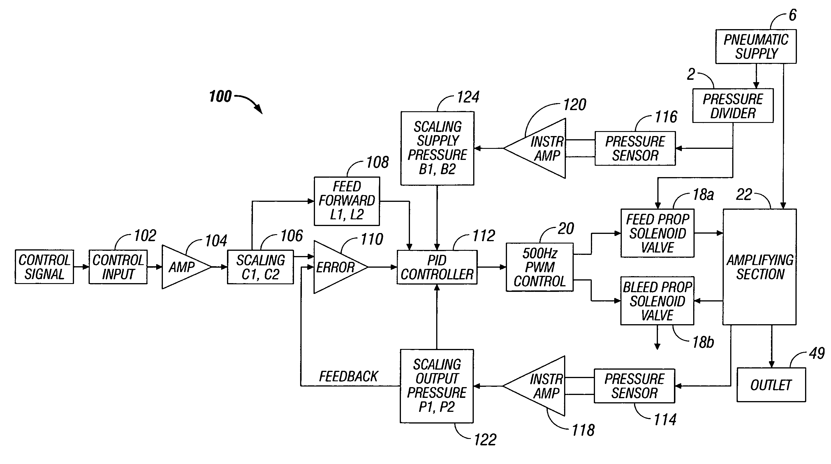
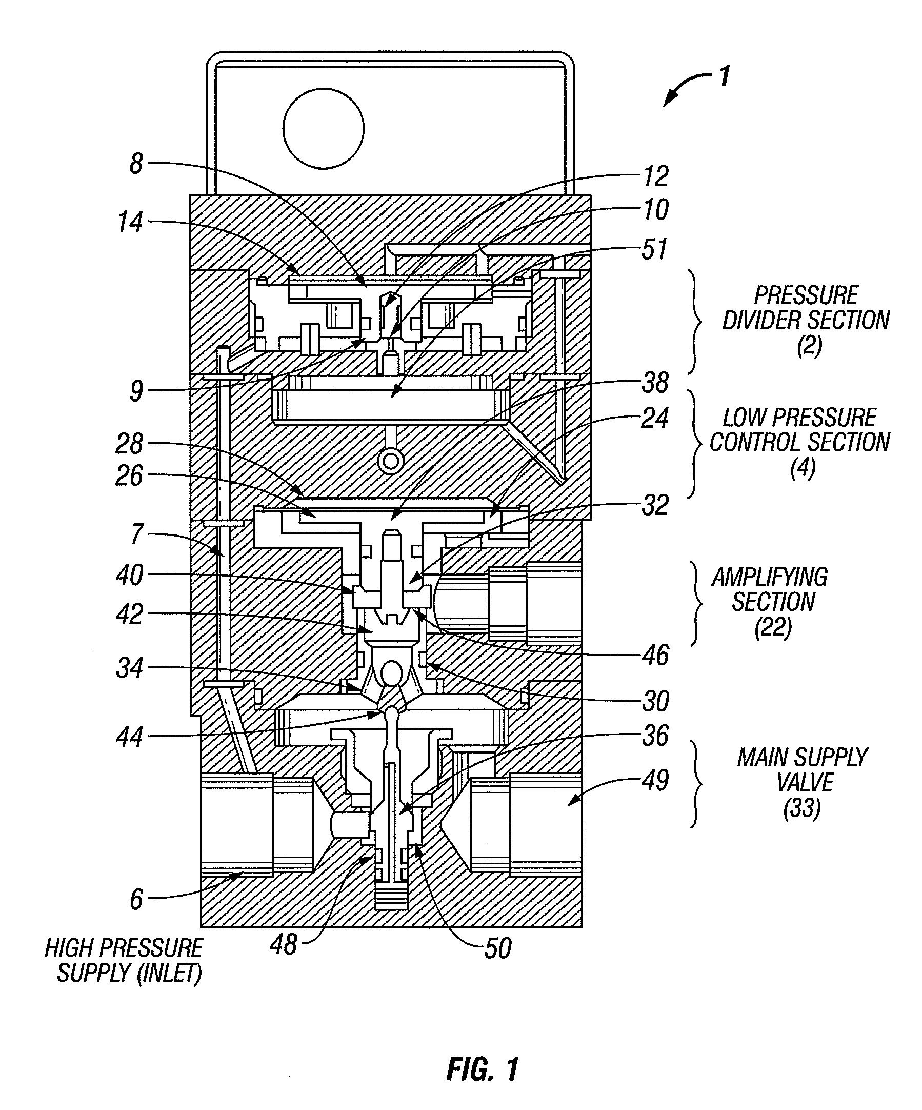
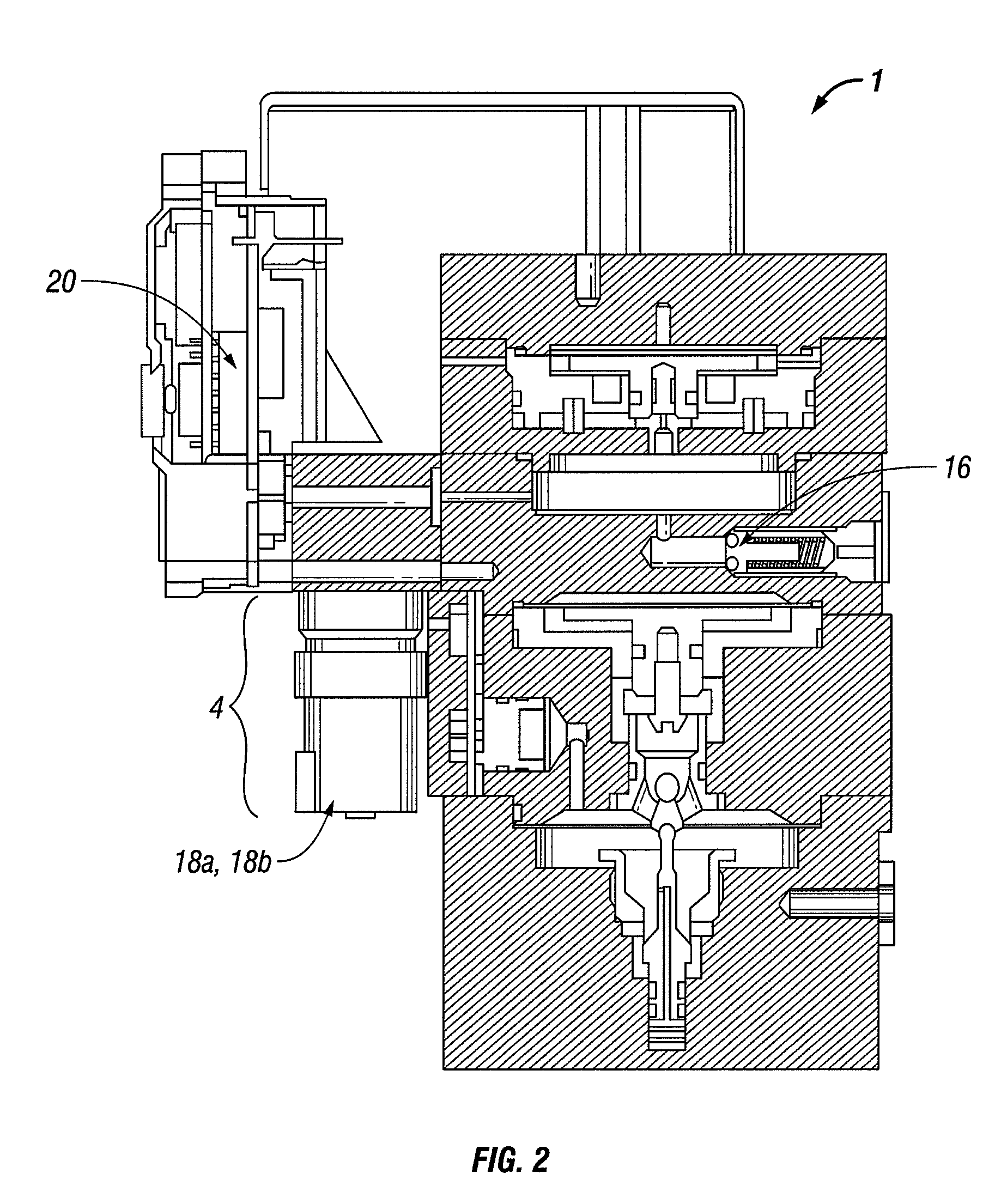
[0021]FIGS. 1 and 2 show a high pressure transducer 1 for controlling flow of a gas. The pressure transducer 1 includes a pressure divider section 2, a low pressure control section 4, an amplifying section 22, and a main supply valve 36. The pressure divider section 2 reduces supply pressure of the gas by a predetermined ratio to a reduced pressure. The reduced pressure gas then operates the low pressure control section 4 which varies the reduced pressure to obtain variable control pressure to actuate the amplifying section 22. More specifically, the low pressure control section 4 includes feed-and-bleed solenoid valves 18a and 18b (FIGS. 2 and 3) as the primary electro-pneumatic conversion mechan...


PUM


Abstract

A high pressure transducer is disclosed. The transducer includes a supply inlet configured to provide a gas supply to the high pressure transducer at a supply pressure and a pressure divider section coupled to the supply inlet. The pressure divider section is configured to reduce the supply pressure to a reduced pressure as a function of a first predetermined ratio. The transducer also includes a low pressure control section coupled to the pressure divider section and configured to receiving the gas supply at the reduced pressure and an amplifying section coupled to the low pressure control section. The low pressure control section varies the reduced pressure to produce a variable control pressure to actuate the amplifying section in response thereto. The amplifying section is also configured to multiply the variable control pressure as a function of a second ratio to obtain an output pressure. Further, the transducer includes a main supply valve coupled to the amplifying section, wherein the amplifying section controls the main supply valve.

Description

CROSS REFERENCE TO RELATED APPLICATION[0001]The present application claims a benefit of priority to U.S. Provisional Application Ser. No. 60 / 832,052 filed on Jul. 20, 2006 entitled “High Pressure Transducer,” the entire contents of which is being incorporated by reference herein.BACKGROUND[0002]1. Field[0003]The present disclosure relates generally to pressure transducers, more specifically to highly responsive gas transducers capable of operating under high pressures.[0004]2. Description of the Related Art[0005]Pressure transducers have advanced significantly in the past few decades driven in part by their demand in machine and process industries. As high performance electronic control interfaces replaced manual pneumatic control interfaces, which required manual inputs to change transducer settings, the demand for high pressure transducers continued to grow accordingly. Although the process industry is satisfied with signal pressures of no more than 30 PSIG, continued drive in aut...

Claims


Application Information

Patent Timeline
Patent Type & Authority Patents(United States)
IPC IPC(8): G05D16/20
CPCF15B5/006Y10T137/2322Y10T137/2409Y10T137/2516Y10T137/2529Y10T137/7758Y10T137/7761Y10T137/7762
Inventor ASKEW, ANDY R.
Owner FIDUS MEZZANINE CAPITAL
Why Eureka
Try Eureka