Transponder with an improved voltage limiter circuit

a transponder and voltage limiter technology, applied in the field of transponders, can solve the problems of relatively easy failure of the response of the reader to the rfid tag b>100/b>, and achieve the effect of improving the operation of the transponder

Active Publication Date: 2010-08-31
NXP BV
View PDF7 Cites 14 Cited by
  • Summary
  • Abstract
  • Description
  • Claims
  • Application Information

AI Technical Summary

Benefits of technology

[0022]The characterizing features according to the invention particularly have the advantage that a transponder is provided in which an antenna coil voltage limit value may be dynamically adjusted. In other words, an antenna voltage limitation may be realized to limit the antenna voltage to different voltage limits in different operation modes of the transponder. By selectively and dynamically adapting the maximally allowed voltage value of the antenna coil to a respective current operation mode, it is possible to efficiently and flexibly adjust the voltage limit so that the performance of the transponder in the respective operation mode can be improved or optimized.
[0023]In contrast to the prior art, the system according to the invention has the advantage that a comparatively low value or limit which may be used for reading does not have to be used for sending as well. For sending, the voltage limit may be adjusted independently and brought to a, for instance, higher value compared to reading. The transmitting range for load modulation (i.e. sending data back to the reader) is thereby increased.
[0024]In any case, this voltage limit should not exceed an upper limit so as to avoid a negative influence on components of the transponder which might be damaged by a high voltage or by heating as a consequence of a high voltage. For instance, components of an integrated circuit which may be part of the transponder can easily be destroyed by large voltages.
[0025]Advantageously, the first voltage limit may be lower than the second voltage limit. A larger voltage swing may thus be utilized to allow communication with a read / write device, even when the read / write device is quite far remote from the transponder. By taking these measures, an increased spatial operation range may be obtained, i.e. a maximum distance through which communication between the transponder and the read / write device may be increased, particularly in an operation mode in which the transponder sends data to the read / write station, as a consequence of an increased modulation depth. Furthermore, the signal-to-noise ratio may be increased as well.

Problems solved by technology

In particular, contactless identification systems such as transponder systems are suitable for wireless transmission of data in a fast manner and without cable connections, which may be disturbing.
This may have the consequence that the recognition of the RFID tag 100 response by the reader is relatively prone to failure.

Method used


Image

  • Transponder with an improved voltage limiter circuit
  • Transponder with an improved voltage limiter circuit
  • Transponder with an improved voltage limiter circuit

Examples


Embodiment Construction

[0046]The illustrations in the drawings are schematic. In these drawings, similar or identical elements are denoted by the same reference signs.

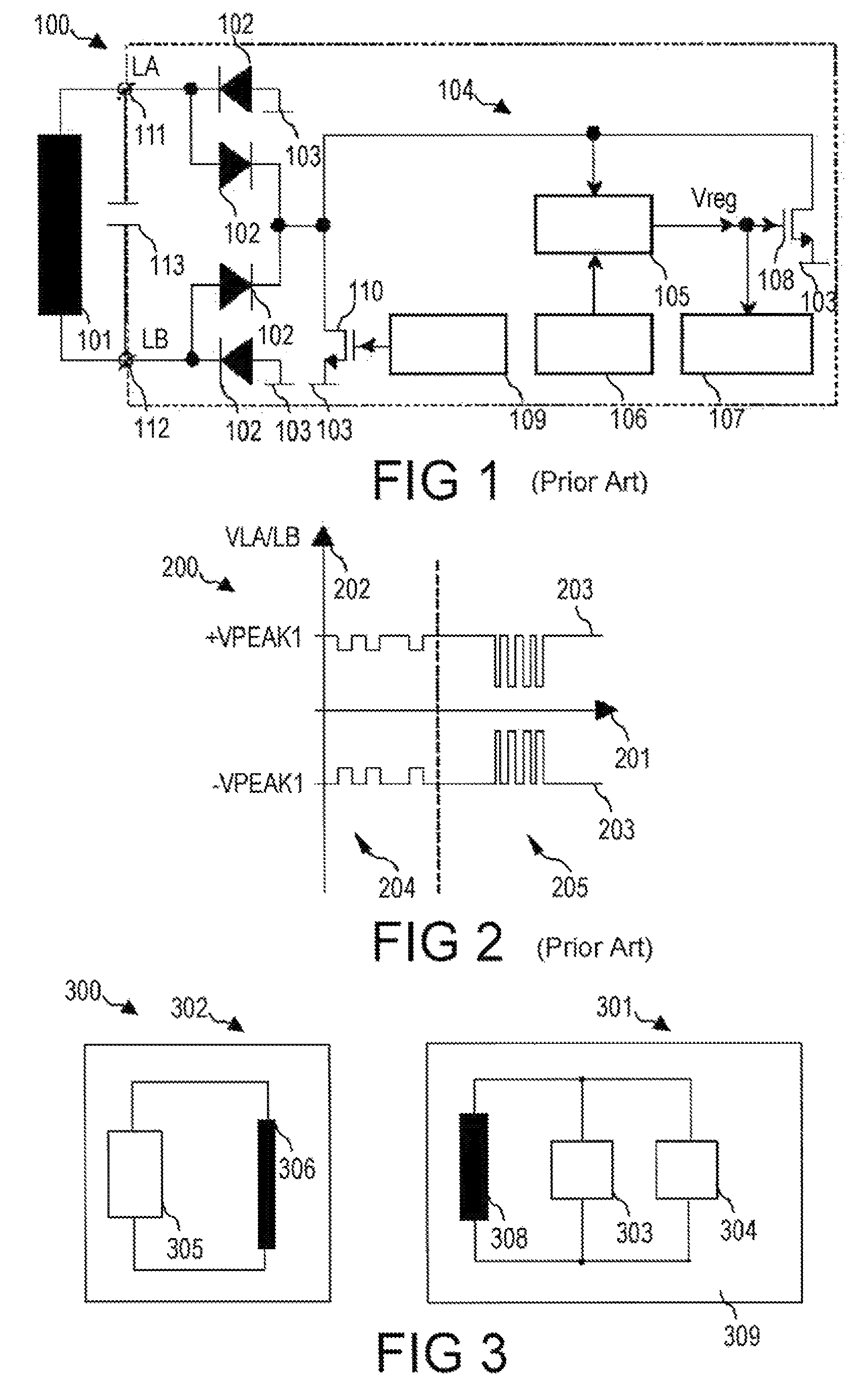
[0047]A transponder system 300 in accordance with an embodiment of the invention will now be described with reference to FIG. 3. The transponder system 300 comprises a transponder 301 and a read / write device 302. The transponder 301 and the read / write device 302 are communicatively coupled in a wireless manner. In other words, communication between the transponder 301 and the read / write device 302 is based on the transmission of electromagnetic radiation in the high-frequency or radio-frequency domain.

[0048]The read / write device 302 is adapted to emit electromagnetic radiation in the high-frequency domain, using a transmitter / receiver coil 306. Furthermore, the transmitter / receiver coil 306 of the read / write device 302 is adapted to receive or detect electromagnetic radiation. When the transponder 301 absorbs energy from such an electromagne...


PUM


Abstract

A transponder with an antenna and an antenna voltage limiting unit for limiting an antenna voltage to a first voltage limit when the transponder is receiving data and to a second voltage limit when the transponder is sending data. Dynamic voltage limitation may be implemented by using a computer program or implemented in hardware. Additionally, it is possible to introduce a third voltage limit when the transponder is in a third mode of operation such as standby or sleeping mode.

Description

FIELD OF THE INVENTION[0001]The invention relates to a transponder, a method of operating a transponder, and a program element.BACKGROUND OF THE INVENTION[0002]The importance of automatic identification systems is growing, particularly in the service sector, and in the fields of logistics, commerce and industrial production. Automatic identification systems are thus implemented more and more in these and other fields and will probably substitute barcode systems in the future. Further applications of identification systems relate to the identification of persons and animals. It is also very interesting to have the possibility of monitoring and controlling a cooling history of food, particularly of perishable food, by using an identification system.[0003]In particular, contactless identification systems such as transponder systems are suitable for wireless transmission of data in a fast manner and without cable connections, which may be disturbing. Such systems use the emission and ab...

Claims


Application Information

Patent Timeline
Patent Type & Authority Patents(United States)
IPC IPC(8): G08B13/14
CPCG06K19/0701G06K19/0723G06K19/07H04B1/59G06K17/00
Inventor ZETTLER, WERNER
Owner NXP BV
Why Eureka
Try Eureka