Antenna module

a technology of antenna module and metal pad, which is applied in the direction of antenna details, antennas, basic electric elements, etc., can solve the problems of inconvenient adjustment inability to accurately adjust and inability to achieve precise control of the length and width of the adjutant metal pad b>17/b>, so as to increase the transmission bandwidth of the low frequency, avoid complex

Inactive Publication Date: 2010-08-31
ADVANCED CONNECTEK INC
View PDF3 Cites 4 Cited by
  • Summary
  • Abstract
  • Description
  • Claims
  • Application Information

AI Technical Summary

Benefits of technology

[0007]In accordance with one aspect of the invention, an antenna module is provided for generating a second low frequency resonant state of the antenna module easily and without complex adjusting processes by increasing spurious radiation conductor so as to increase transmission bandwidth of the low frequency and overcome disadvantages in conventional low frequency resonant structure. In addition, the structure of the antenna module is simple so that the antenna is with great precision and convenient manufacturing process.
[0008]In accordance with one aspect of the invention, an antenna module is provided. The antenna module, having a spurious radiation conductor with a first radiation piece and a second radiation piece, increases the matching efficiency of the antenna resonant state by adjusting resistance of the antenna module. Therefore, the antenna module is with better resistance bandwidth.
[0010]The antenna module excites a high frequency resonant state by the first radiation conductor and generates a first low frequency resonant state via the extending portion and the s / c element. In addition, a second low frequency resonant state of the antenna module is conducted so as to increase the transmission bandwidth of the low frequency bandwidth. The radiation plate is applied by metal wires or metal patches and the terminals of the first radiation piece and the second radiation piece are with a gap between each other in parallel. The gap is applied for generating capacitor coupling effect so as to increase the resistance efficiency of the low frequency resonant state of the antenna module.

Problems solved by technology

However, the adjutant metal pad 17 is a C-shape piece and the modification must be conducted by bending whole metal pad, so that the adjutant process is not easy to execute.
Therefore, the transmission bandwidth of its low-frequency base band is limited easily.
In addition, the exactness for adjusting the length and width of the adjutant metal pad 17 is not easy to control.
In conclusion, it's difficult to implement the production of the antenna and hard to accomplish the efficiency it claimed.

Method used


Image

  • Antenna module
  • Antenna module
  • Antenna module

Examples


first embodiment

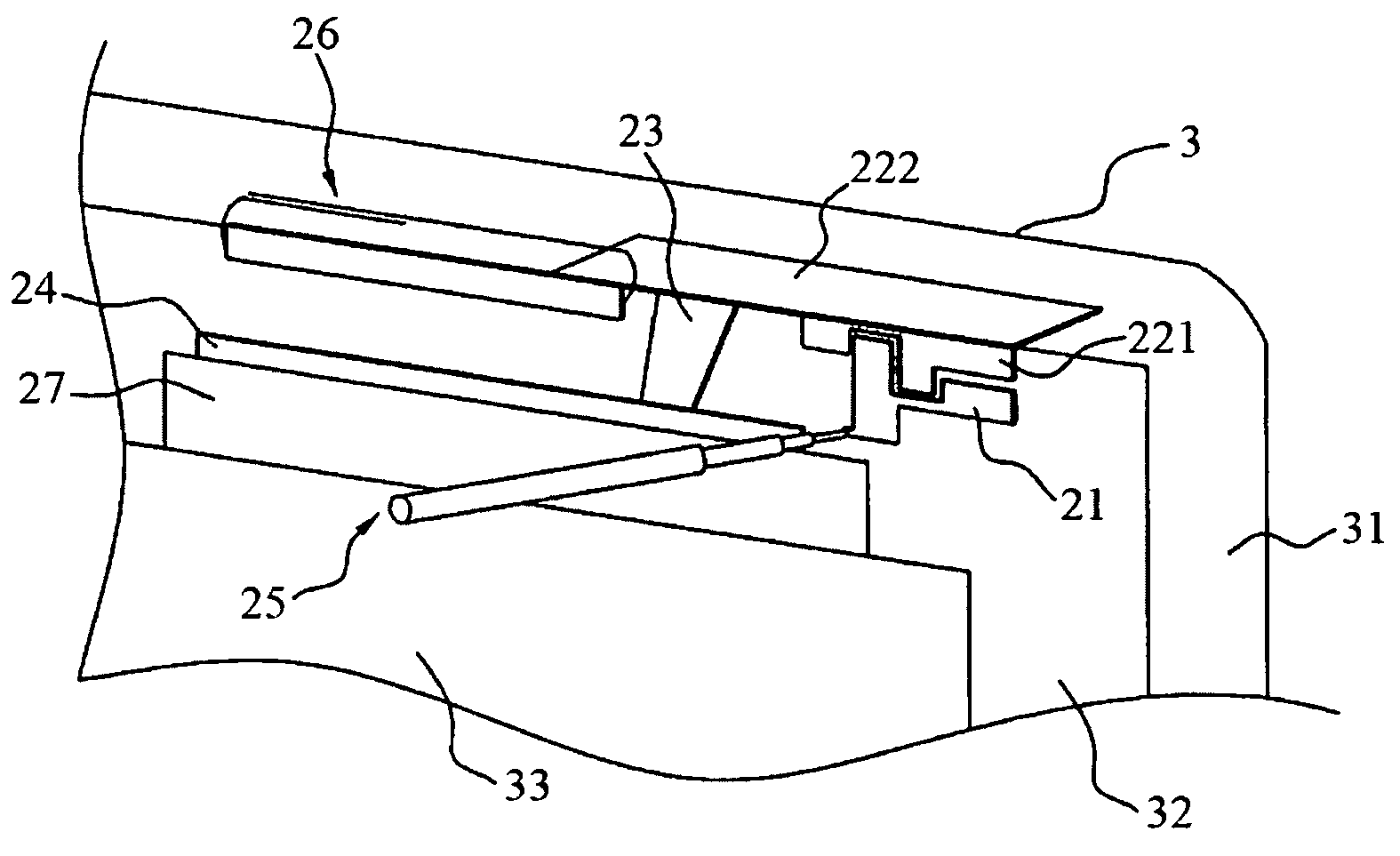
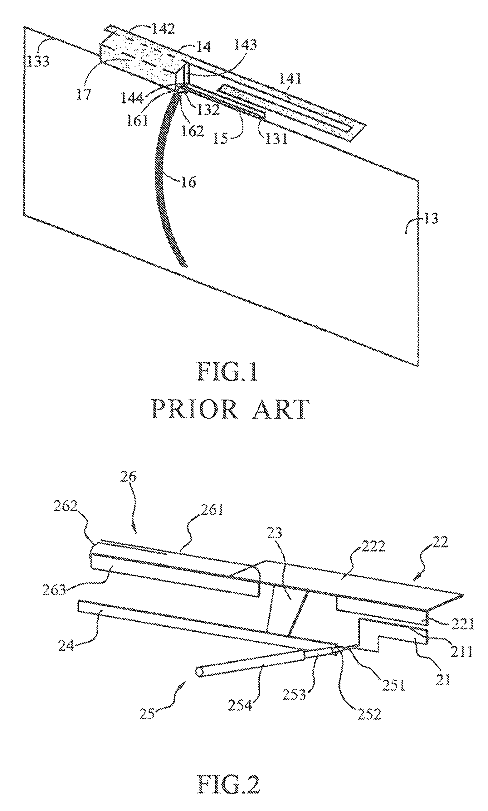
[0020]Please refer to FIG. 2, a three-dimension view of an antenna module according to the present invention is illustrated. The antenna module comprises a first radiation conductor 21, a second radiation conductor 22, an s / c element 23, a ground plane 24, a feed-in cable 25 and a spurious radiation conductor 26.

[0021]The first radiation conductor 21, similarly to L-shape, further comprises a bottom side 211. The second radiation conductor 22 comprises a coupled portion 221 and an extending portion 222, a side margin of the coupled portion 221 is configured near the bottom side 211 of the first radiation conductor 21 with a gap, wherein the counter side is connected to the extending portion 222. The coupled portion 221 and extending portion 222 are vertical with each other. The s / c element 23, similarly to T-shape, is connected to the extending portion 222 with one terminal and connected to the ground plane 24 with another terminal. The feed-in cable 25, transmitting electrical sign...

second embodiment

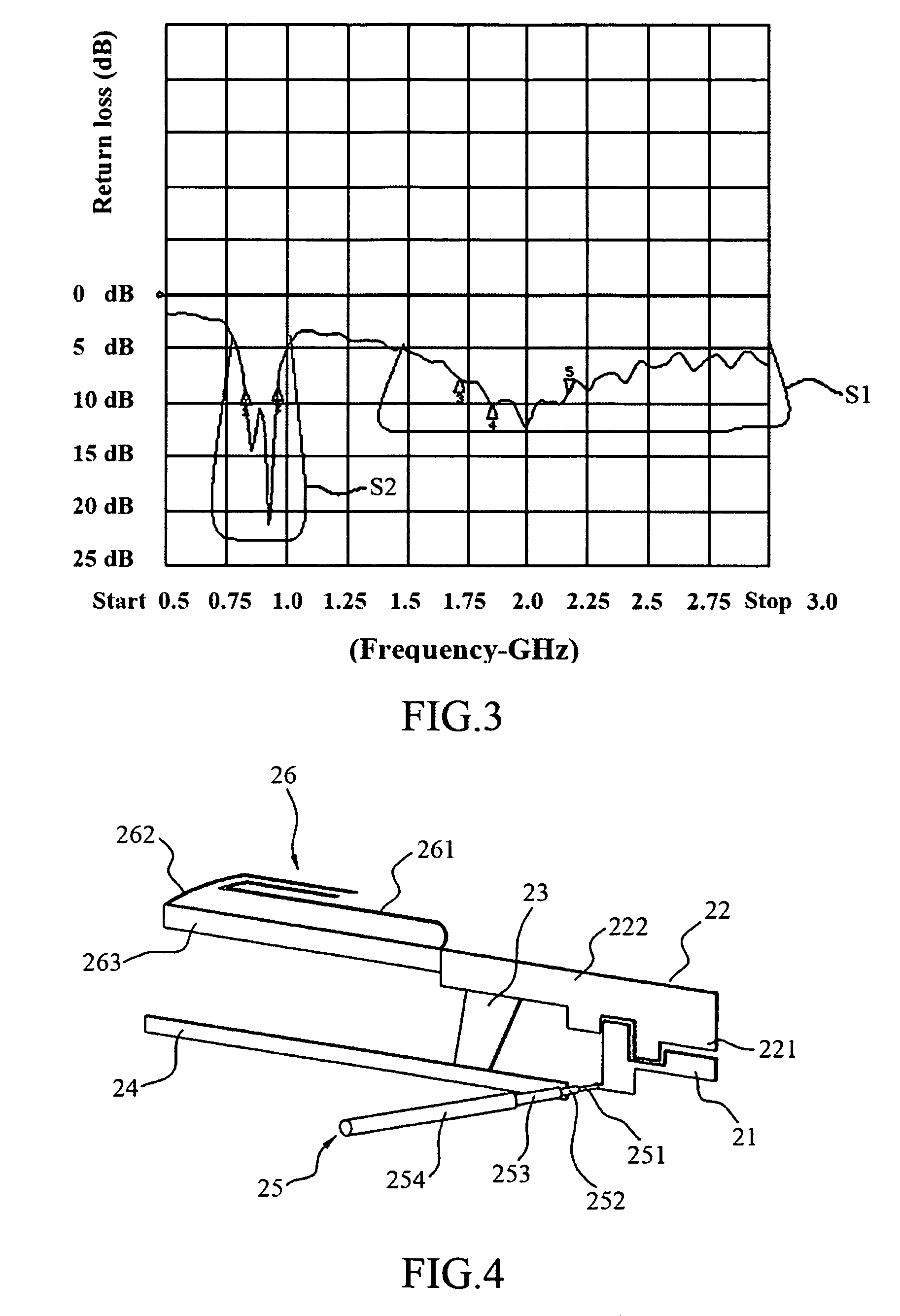
[0027]Please referring to FIG. 4, a three-dimension view of an antenna module according to the present invention is illustrated. The gap between the coupled portion 221 and the first radiation conductor 21 is shaped with multiple curves. When the feed-in signal of the first radiation conductor 21 is coupled to the coupled portion 221, the efficiency of electrical coupled effect is increased by extending the electrical coupler path and the electrical coupler of the multiple curves gap according to the electrical coupled effect. The extending portion 222 is also capable of locating at the same plane with the coupled portion 221 and in parallel with each other. The first radiation piece 261 is configured at a location near the connecting portion between the extending portion 222 and the spurious radiation plate 263. The first radiation piece 261 and the second radiation piece 262 may be applied with metallic material so as to increase radiation transmission efficiency of the antenna mo...


PUM


Abstract

An antenna module is provided. The antenna module comprises a first radiation conductor, a second radiation conductor, a short-circuit element (s / c element), a ground plane, a feed-in cable and a spurious radiation conductor. One terminal of the second radiation conductor is near the first radiation conductor with a gap. One terminal of the s / c element is connected to the second radiation conductor and the other side of the s / c element is connected to the ground plane. The feed-in cable comprises a centre conductor and an external conductor, wherein the centre conductor is connected to the first radiation conductor and the external conductor is connected to the ground plane. The spurious radiation conductor is connected to the second radiation conductor. The second radiation conductor comprises a spurious radiation plate, a first radiation piece and a second radiation piece within the two sides of the second radiation conductor. The first radiation piece and a second radiation piece are in parallel and a gap is conducted between the first radiation piece and the second radiation piece.

Description

TECHNICAL FIELD[0001]The present invention relates to an antenna module, and more particularly, to an antenna module with a spurious radiation conductor for generating low frequency resonant states.BACKGROUND ART[0002]In the case of mobile phone, the optimal resonant length for conventional resonant dipole antenna or patch antenna should be half of wavelength. If a wavelength is conducted according to the base band at 900 MHz, above wavelength is not implemental inside a cell phone. However, it could be overcome after a Planar Inverted-F Antenna is applied within. The Planar Inverted-F Antenna realizes an optimal resonant length with a quarter of wavelength mainly by using a shorting pin so as to place the antenna into the cell phone. However, when the shorting pin is applied, variations of resistances among the shorting pin are increased. That would narrow the bandwidth of the antenna down relatively. Therefore, metal shorting plate and metal shorting wall are designed for better b...

Claims


Application Information

Patent Timeline
Patent Type & Authority Patents(United States)
IPC IPC(8): H01Q1/24H01Q1/38
CPCH01Q1/2266H01Q9/0421
Inventor TSENG, YI-WEICHIU, TSUNG-WENHSIAO, FU-RENLIN, SHENG-CHIH
Owner ADVANCED CONNECTEK INC
Why Eureka
Try Eureka