Lamp unit for vehicles

a technology for lamps and vehicles, applied in transportation and packaging, semiconductor devices for light sources, lighting and heating apparatus, etc., can solve the problems of not meeting the demands of reducing depth dimension, and reducing horizontal depth dimension, etc., to achieve good vision identifization

Inactive Publication Date: 2010-11-16
ICHIKOH IND LTD
View PDF15 Cites 2 Cited by
  • Summary
  • Abstract
  • Description
  • Claims
  • Application Information

AI Technical Summary

Benefits of technology

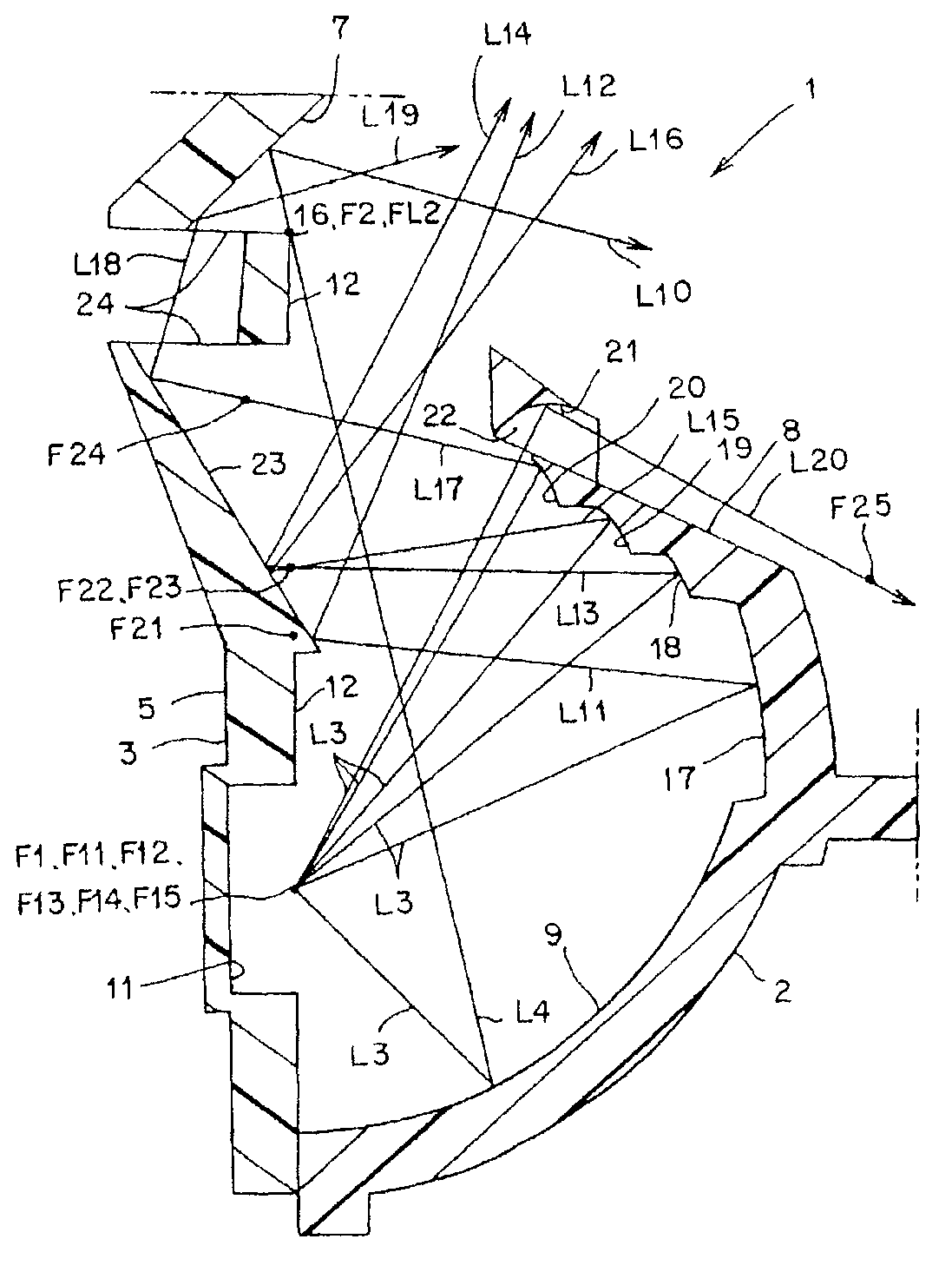
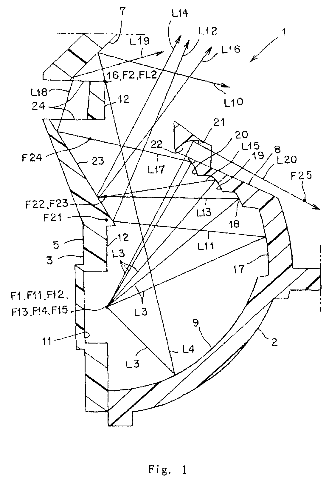
[0017]The lamp unit for vehicles according to the present invention (Solution 1 of the present invention) is the one in which the planar reflect surface is arranged between the projection lens and its focus in such a way that the planar reflect surface intersects the light axis of the projection lens, as a result of which, at the symmetrical position with respect to the planar reflect surface by way of the planar reflect surface, the lens focus of the projection lens exists as a fictitious lens focus positioned at the second focus of the ellipse reflect surface, and the horizontal lens light axis of the projection lens exists as the fictitious light axis of the lens that is vertical and intersects the light axis of the lens orthogonally by way of the planar reflect surface, the fictitious light axis of the lens being consistent with the light axis of the ellipse reflect surface. Therefore, in the lamp unit for vehicles according to the present invention (Solution 1 of the present invention), the projection lens and the planar reflect surface can be arranged in the horizontal direction, and the projection lens, the planar reflect surface, the reflector, the semiconductor light source, and the shade are arranged in the vertical direction, and thus the lamp unit for vehicles according to the present invention (Solution 1 of the present invention) can reduce the depth dimension in the horizontal direction and the height dimension in the vertical direction, and can meet the demands for reducing the depth dimension and the height dimension.
[0018]Furthermore, in the lamp unit for vehicles according to the present invention (Solution 1 of the present invention), the light shutout member for shutting out the straight light from the semiconductor light source from illuminating toward the projection lens, is arranged between the semiconductor light source and the projection lens, and therefore, the light except the predetermined distributed light pattern projected from the projection lens, i.e. the light not distributed, can be prevented from emitting from the projection lens, which is advantageous to the transportation safety. In addition, the lamp unit for vehicles according to the present invention (Solution 1 of the present invention) can shut out the outer light illuminating from the projection lens toward the side of the ellipse reflection surface at the side of the semiconductor light source by the light shutout member arranged between the semiconductor light source and the projection lens, as result of which, the lamp unit for vehicles according to the present invention (Solution 1 of the present invention) can prevent the dubitable lighted light resulting from the circumstance where the outer light is reflected by the ellipse reflect surface and thus emits outwardly from the projection lens, leading to the semiconductor light source seeming to be lighted even though it is not lighted.
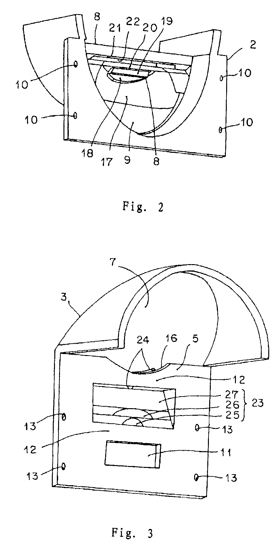
[0019]Moreover, because, in the lamp unit for vehicles according to the present invention (Solution 1 of the present invention), the light shutout member is provided with the supplemental reflect surface for reflecting the light from the semiconductor light source toward the side of the shade, and the shade is provided with the through hole for the reflected light from the supplemental reflect surface to go through and toward the planar reflect surface, the light from the semiconductor light source can be effectively used by way of the supplemental reflect surface of the light shutout member and the through hole of the shade.
[0021]Furthermore, because, in the lamp unit for vehicles according to the present invention (Solution 3 of the present invention), the first supplemental reflect surface comprises the ellipse reflect surface, the distributed light pattern for the overhead sign is evenly distributed and the distributed light pattern with good vision identifization for the overhead sign can be obtained.

Problems solved by technology

Because of this reason, the existing lamp unit for vehicles can not meet the demands for reducing the depth dimension.
Therefore, because, in this type of lamp unit for vehicles, the electricity discharge lamp bulb, the reflector, the projection lens, and the planar reflect surface are arranged in the direction of the front and the rear of the vehicle, the depth dimension in the horizontal direction becomes big, just as the lamp unit for vehicles mentioned in Patents 1-3, and it can not meet the demands for reducing the depth dimension.
However, this type of existing lamp unit for vehicles is not the projector type of lamp unit for vehicles that does not use projection lens.
And moreover, because this type of existing lamp unit for vehicles is the one in which the light axis of the first reflector intersects the light axis of the second reflector, the height dimension in the vertical direction increases at the same time the depth dimension in the horizontal direction reduces, and thus it can not meet the demands for reducing the depth dimension and the height dimension.
Furthermore, the existing lamp unit for vehicles mentioned above do not take into consideration the method of preventing the light, except the predetermined distributed light pattern projected from the projection lens, from emitting from the projection lens, and therefore, there exists the circumstance where the light except the predetermined distributed light pattern projected from the projection lens, i.e. the light not distributed, emits from the projection lens.
In addition, the existing lamp unit for vehicles mentioned above do not take into consideration the method of the effective use of the light from semiconductor light source, and therefore, the existing lamp unit for vehicles mentioned above do not effectively use the light from semiconductor light source.

Method used


Image

  • Lamp unit for vehicles
  • Lamp unit for vehicles
  • Lamp unit for vehicles

Examples


Embodiment Construction

[0030]The detailed explanation of the lamp unit for vehicles of the embodiments according to the present invention is now given with reference to the drawings. In addition, the present invention is not limited to the embodiments. In the specification, the words “front, rear, up, down, left, right” mean the “front, rear, up, down, left, right” of the vehicle when the lamp unit for vehicles is mounted on the vehicle. In the drawings, the mark “VU-VD” means the up-down vertical line of the paper surface. The mark “HL-HR” means the left-right horizontal line of the paper surface. In addition, in the scope of the specification and the claims, “horizontal” means “horizontal or roughly horizontal”, and “vertical” means “vertical or roughly vertical”.

[0031]Now the explanation of the structure of the lamp unit for vehicles of the embodiment is given. In the figures, mark 1 is the lamp unit for vehicles in the embodiment which is, for example, the head lamp of the vehicle. The lamp unit for v...


PUM


Abstract

In existing lamp unit for vehicles, the light from the semiconductor light source can not be effectively used. In the present invention, a shade (5) is arranged between the second focus (F2) of a first reflect surface (9) and a semiconductor light source (4), for cutting off a portion of the reflected light (L4) emitting from the semiconductor light source (4) and reflected by the first reflect surface (9), and using the remaining reflected light (L4) to form a predetermined distributed light pattern (P) having the cutoff lines (CL); a light shutout member (8) is provided with the fourth part (20) of the supplemental reflect surface for reflecting the light (L3) from the semiconductor light source (4) toward the shade (5); a through hole (24) is arranged on the shade (5) for the reflected light (L17) from the fourth part (20) of the supplemental reflect surface illuminating therethrough toward the planar reflect surface (7). As a result, as a distributed light pattern P4 for a overhead sign, the light (L3) from the semiconductor light source (4) can be effectively used.

Description

FIELD OF THE INVENTION[0001]The present invention relates to a projector type of lamp unit for vehicles using a semiconductor light source, for example LED and the like, as a light source, especially to a lamp unit for vehicles that can be used as a vertical projector lamp whose depth dimension and height dimension can be miniaturized, can prevent the light except the predetermined distributed light pattern projected from a projection lens, i.e. the light not distributed, from emitting from the projection lens, and can effectively use the light from semiconductor light sources.BACKGROUND OF THE INVENTION[0002]There exists the type of lamp unit for vehicles (for example, Patent 1, Patent 2, and Patent 3). The explanation of the existing lamp unit for vehicles is given now. The existing lamp unit for vehicles includes a reflector having an ellipse reflect surface, a semiconductor light source, for example LED and the like, arranged in such a way that its light emitting part is positio...

Claims


Application Information

Patent Timeline
Patent Type & Authority Patents(United States)
IPC IPC(8): F21V11/00
CPCF21S48/1159F21S48/1163F21S48/1258F21S48/145F21S48/1335F21Y2101/02F21Y2115/10F21S41/143F21S41/155F21S41/255F21S41/323F21S41/43F21W2102/18
Inventor NISHIHATA, KOJI
Owner ICHIKOH IND LTD
Why Eureka
Try Eureka