Disk conveying means for a disc drive using retractable rollers and guide plates

a technology of disc drives and conveying means, which is applied in the direction of data recording, instruments, record carrier contruction details, etc., can solve the problems of increasing and achieve the effect of reducing shortening the depth dimension of the disk apparatus, and reducing the size of the whole disk apparatus

Inactive Publication Date: 2008-09-02
MITSUBISHI ELECTRIC CORP
View PDF20 Cites 0 Cited by
  • Summary
  • Abstract
  • Description
  • Claims
  • Application Information

AI Technical Summary

Benefits of technology

[0009]In accordance with the present invention, the disk apparatus is so constructed as to, when retracting the guide mechanism toward the disk insertion / ejection opening, move the disk conveying mechanism in a direction which intersects with the direction of conveyance of the disk. As a result, an area to which the disk conveying mechanism is retracted can be lessened. Therefore, shortening of the depth dimension of the disk apparatus can be achieved, and downsizing of the whole of the disk apparatus can be achieved.

Problems solved by technology

A problem with the related art disk apparatus is that since in order to retract the disk conveying mechanism, disk conveying rollers separately disposed on right-hand and left-hand sides of the disk conveying mechanism are made to horizontally rotate around supporting portions formed at ends thereof and to retract toward a disk insertion / ejection opening, there is a necessity to provide a large retraction area toward which the disk conveying rollers are retracted, and the whole of the disk apparatus increases in size.

Method used


Image

  • Disk conveying means for a disc drive using retractable rollers and guide plates
  • Disk conveying means for a disc drive using retractable rollers and guide plates
  • Disk conveying means for a disc drive using retractable rollers and guide plates

Examples


embodiment 1

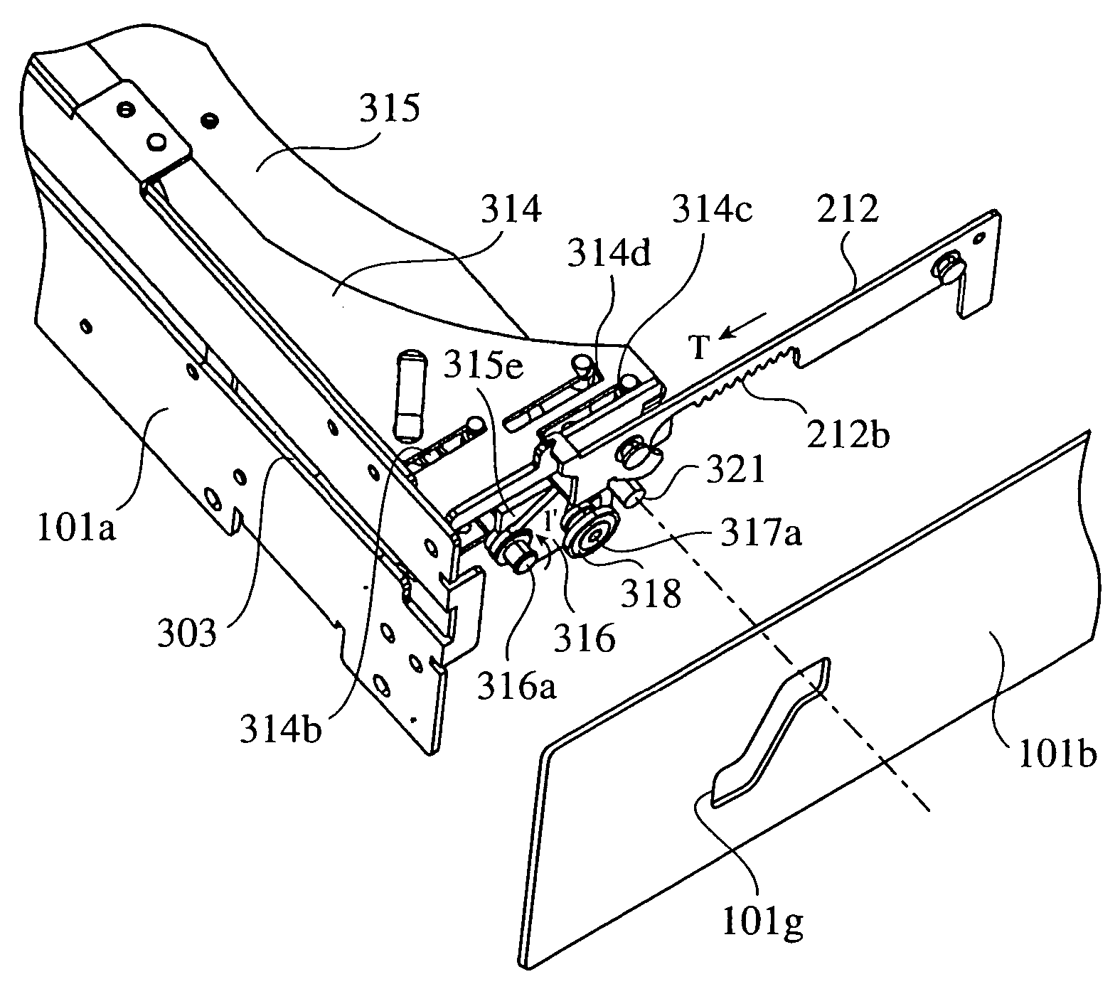
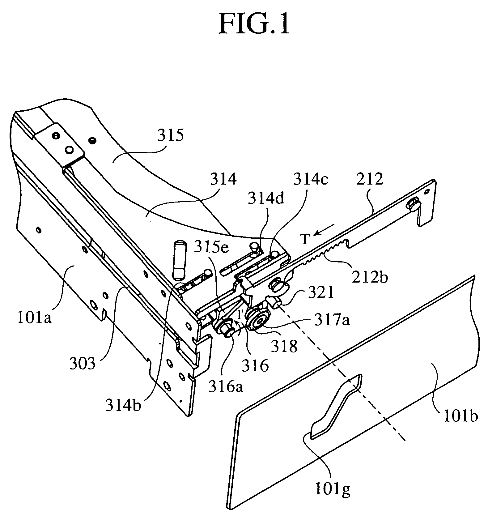
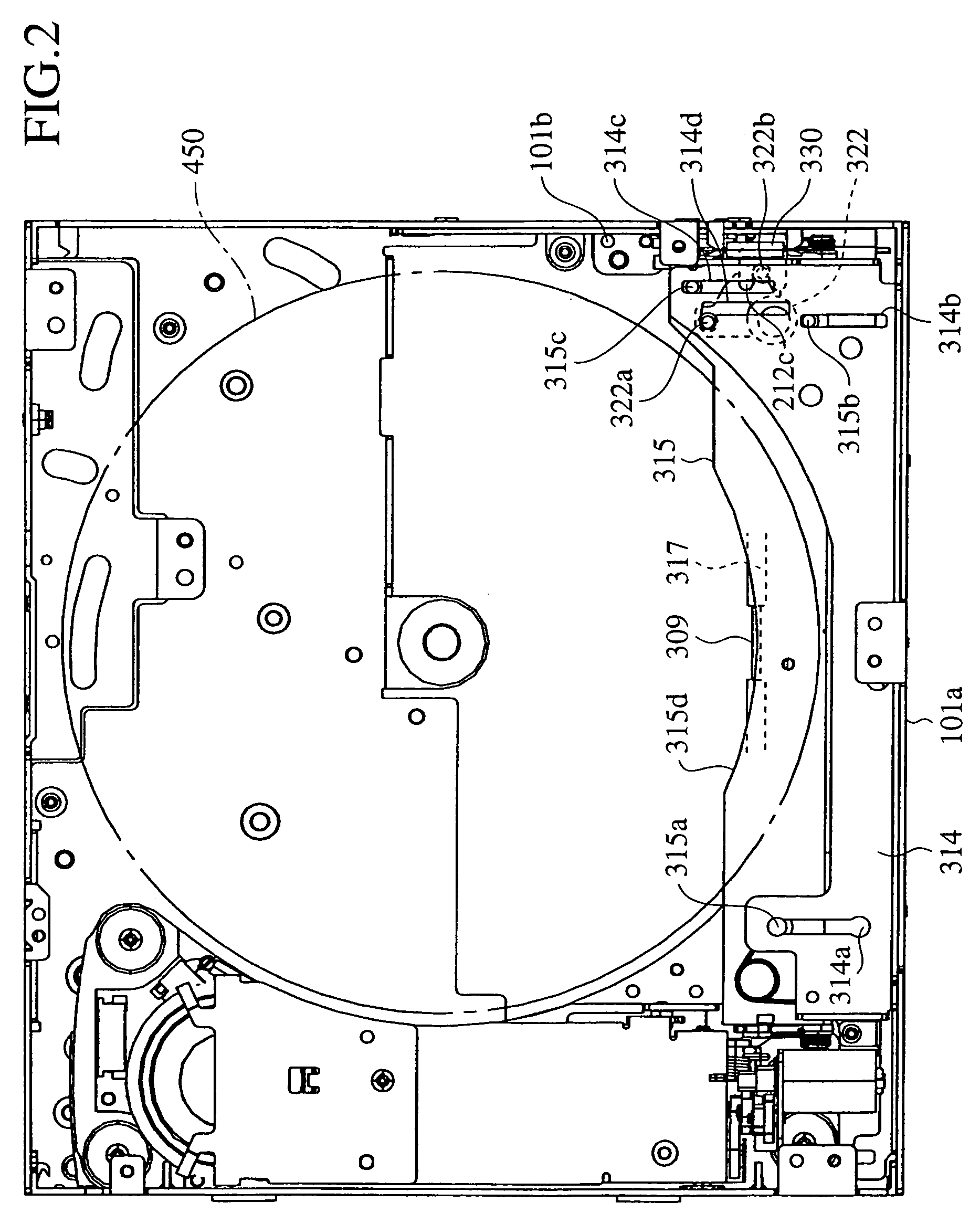
[0045]FIG. 1 is a perspective diagram of a main part of a disk apparatus in accordance with the present invention, FIG. 2 is a plan view showing a state in which a disk is conveyed into the disk apparatus, FIG. 3 is a side view of a disk conveying mechanism in the state of FIG. 2, FIG. 4 is a plan view showing a state in which the disk conveying mechanism is retracted toward a disk insertion / ejection opening after a disk has been conveyed into the disk apparatus, and FIG. 5 is a side view of the disk conveying mechanism in the state of FIG. 4.

[0046]As shown in FIGS. 1 and 2, the disk conveying mechanism has a base plate 314 that is disposed above the disk insertion / ejection opening 303 formed in a front side plate 101a of a housing and that is projecting from an inner surface of the front side plate 101a of the housing to the interior of the housing, and a plurality of straight line-shaped guide grooves 314a to 314c and an L-shaped guide groove 314d are formed in both end portions o...


PUM

PropertyMeasurementUnit
anglesaaaaaaaaaa
anglesaaaaaaaaaa
anglesaaaaaaaaaa

Abstract

A disk apparatus includes a guide mechanism for guiding conveyance of a disk so that the disk can be advanced or retracted in a direction of conveyance of the disk, rotary members rotatably disposed on both ends of the guide mechanism, a disk conveying mechanism disposed opposite to the guide mechanism between the rotary members, and a rotating mechanism for, when retracting the guide mechanism toward a disk insertion / ejection opening, rotating the rotary member so as to move the disk conveying mechanism in a direction which intersects with the direction of conveyance of the disk.

Description

BACKGROUND OF THE INVENTION[0001]1. Field of the Invention[0002]The present invention relates to a disk apparatus that plays back information stored in a disk. More particularly, it relates to a disk apparatus that can be used with being mounted in a moving object, such as a motor vehicle.[0003]2. Description of Related Art[0004]Such a disk apparatus is provided with a disk conveying mechanism for conveying a disk inserted into a housing thereof to a playback position, and retracts the disk conveying mechanism to a position where it does not interferes with the inserted disk at the time of playing back the disk. Conventionally, as disclosed in patent reference 1, in order to retract the disk conveying mechanism, disk conveying rollers separately disposed on right-hand and left-hand sides of the disk conveying mechanism are made to horizontally rotate around supporting portions formed at ends thereof and retract toward a disk insertion / ejection opening.[0005][Patent reference 1] JP,1...

Claims


Application Information

Patent Timeline
Patent Type & Authority Patents(United States)
IPC IPC(8): G11B7/085G11B17/04G11B17/26G11B17/00G11B17/03G11B17/22G11B21/08G11B33/02
CPCG11B17/225G11B17/05
Inventor TANIGUCHI, KAZUTOSHI
Owner MITSUBISHI ELECTRIC CORP
Why Eureka
Try Eureka