Image processing apparatus

a technology for processing apparatus and image, applied in the field of image processing apparatus, can solve the problems of troublesome user feeding recording media, lowering operability, and difficulty in placing the apparatus in a relatively narrow space, and achieve the effect of lowering operability, reducing the depth dimension of the apparatus as a whole, and reducing the size of the apparatus

Active Publication Date: 2016-10-04
BROTHER KOGYO KK
View PDF8 Cites 0 Cited by
  • Summary
  • Abstract
  • Description
  • Claims
  • Application Information

AI Technical Summary

Benefits of technology

[0007]The apparatus in which the cover is provided at its upper side and the supporter for supporting the recording medium (hereinafter simply referred to as “supporter” where appropriate) is provided on a rear side of the apparatus suffers from the following disadvantages. When comparison is made between two apparatuses respectively having covers with mutually the same depth dimension, the apparatus having the supporter on its rear side has a depth dimension of the apparatus as a whole larger than that of the apparatus not having the supporter. In this case, the apparatus is large-sized in the depth direction, making it difficult to place the apparatus in a relatively narrow space.
[0008]When comparison is made between two apparatuses having mutually the same depth dimension of the apparatus as a whole, the depth dimension of the cover is smaller in the apparatus having the supporter on its rear side than in the apparatus not having the supporter. In this case, when a user pivots the cover to the open position and places an original on the platen, the cover having a smaller depth dimension needs to be pivoted at a larger pivot angle in an instance where the cover is moved away from the platen by the same distance, resulting in lowered operability.
[0009]By reducing the depth dimension of the supporter, the depth dimension of the apparatus as a whole can be accordingly reduced without changing the depth dimension of the cover. It is thus possible to downsize the apparatus while preventing deterioration in the operability of the cover. By reducing the depth dimension of the supporter, the depth dimension of the cover can be accordingly increased without changing the depth dimension of the apparatus as a whole. It is thus possible to improve the operability of the cover while preventing upsizing of the apparatus. The reduction in the depth dimension of the supporter, however, results in a reduction in the amount of the recording media that can be set on the supporter. This leads to another disadvantage that it is troublesome for a user to feed the recording media to the supporter when printing is successively performed on a large number of recording media.
[0010]An aspect of the disclosure relates to an image processing apparatus in which a plurality of recording media can be set on a supporter provided on a specific side of the apparatus and which can achieve, at the same time, downsizing of the apparatus and improvement of the operability when an upper portion of the apparatus is opened and closed.

Problems solved by technology

In this case, the apparatus is large-sized in the depth direction, making it difficult to place the apparatus in a relatively narrow space.
In this case, when a user pivots the cover to the open position and places an original on the platen, the cover having a smaller depth dimension needs to be pivoted at a larger pivot angle in an instance where the cover is moved away from the platen by the same distance, resulting in lowered operability.
This leads to another disadvantage that it is troublesome for a user to feed the recording media to the supporter when printing is successively performed on a large number of recording media.

Method used


Image

  • Image processing apparatus
  • Image processing apparatus
  • Image processing apparatus

Examples


Embodiment Construction

[0022]There will be hereinafter described an image processing apparatus according to one embodiment.

Structure of Image Processing Apparatus

[0023]Structure of MFP

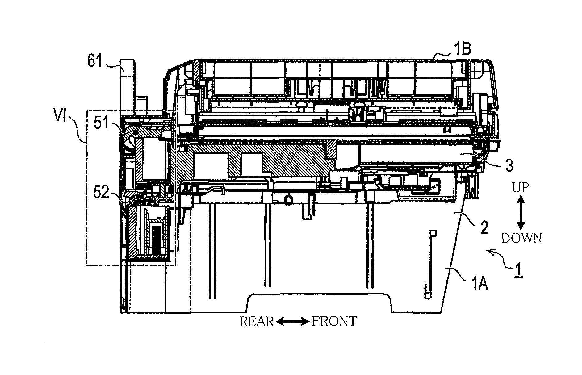
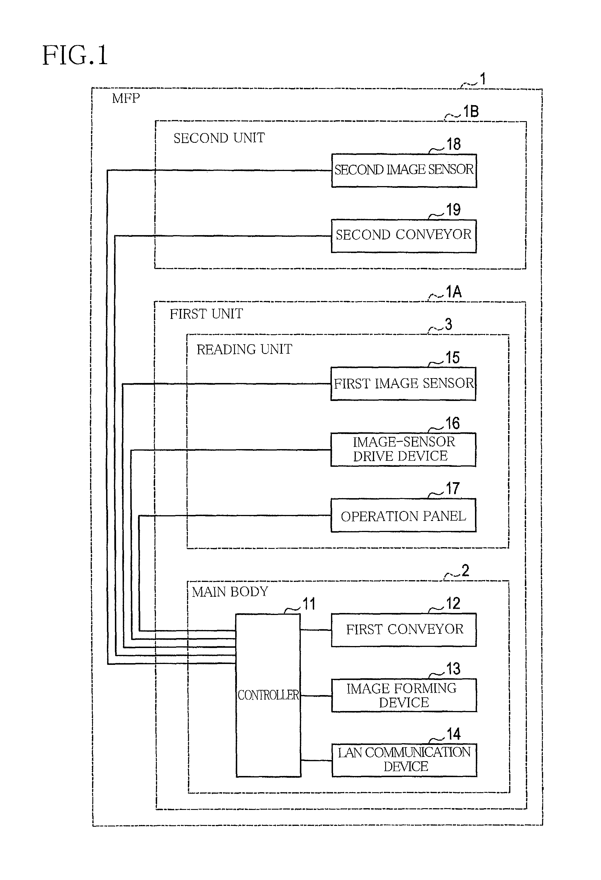
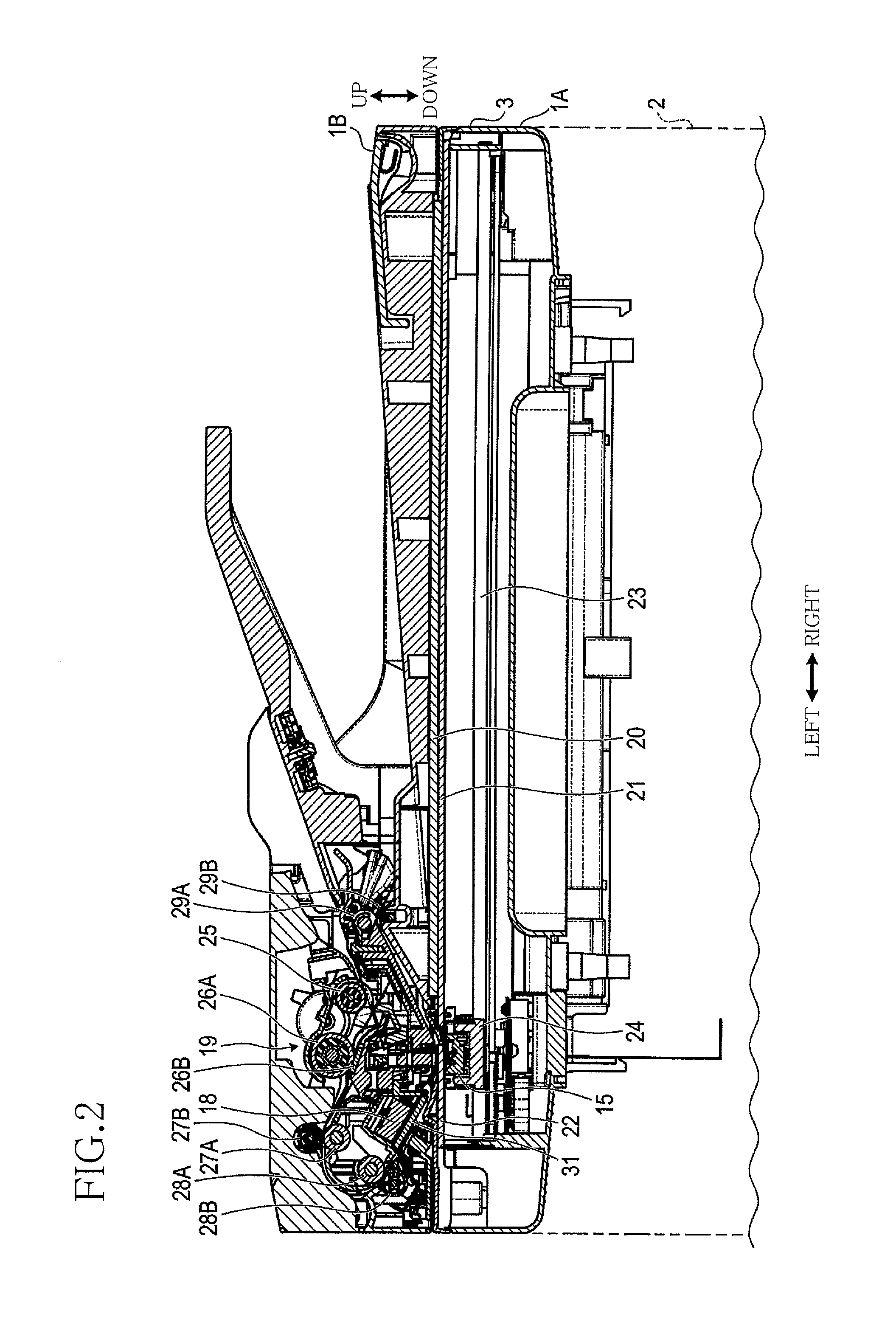
[0024]A multifunction peripheral (MFP) 1 shown in FIG. 1 has a structure corresponding to one example of the image processing apparatus described above. As shown in FIG. 1, the MFP 1 includes a first unit 1A and a second unit 1B. The first unit 1A includes a main body 2 and a reading unit 3. In the main body 2, a controller 11, a first conveyor 12, an image forming device 13, and a LAN communication device 14 are disposed. In the reading unit 3, a first image sensor 15, an image-sensor drive device 16, and an operation panel 17 are disposed. The first image sensor 15 and the image-sensor drive device 16 are one example of “image reader”. In the second unit 1B, a second image sensor 18 and a second conveyor 19 are disposed.

[0025]The controller 11 includes a CPU, a ROM, and a RAM which are known in the art. The CPU executes pr...


PUM


Abstract

An image processing apparatus, including: a first unit; a second unit; and a pair of first hinges spaced apart from each other in a first direction, the first and second units being coupled through the hinges, wherein the first unit includes a supporter for supporting a recording medium and a first conveyor including a supply roller and configured such that, in a state in which recording media are set on the supporter, the first conveyor conveys the media one by one by the supply roller toward a downstream side in a conveyance direction, wherein the supporter is configured to be pivotally movable between a housed position and a use position about an axis extending, on a specific side of the first unit, in a direction parallel to the first direction, and wherein the supporter is disposed between the first hinges at least when located at the housed position.

Description

CROSS REFERENCE TO RELATED APPLICATION[0001]The present application claims priority from Japanese Patent Application No. 2015-038851, which was filed on Feb. 27, 2015, the disclosure of which is herein incorporated by reference in its entirety.BACKGROUND[0002]1. Technical Field[0003]The following disclosure relates to an image processing apparatus.[0004]2. Description of the Related Art[0005]There is known an image processing apparatus having an image forming device for forming an image on a recording medium and configured to supply the recording medium from a specific side (e.g., a rear side) of the apparatus. For instance, the known apparatus includes a supporter provided on the side of the apparatus for supporting the recording medium. A plurality of recording media can be set on the supporter. The recording media set on the supporter are supplied one by one by a supply roller provided on the side of the apparatus to the image forming device.[0006]The known apparatus includes an ...

Claims


Application Information

Patent Timeline
Patent Type & Authority Patents(United States)
IPC IPC(8): B41J11/00H04N1/00
CPCB41J11/007H04N1/00522H04N1/00554H04N1/00559H04N2201/0094
Inventor MIURA, KATSUROSAMOTO, KENJI
Owner BROTHER KOGYO KK
Why Eureka
Try Eureka