Eureka AIR delivers breakthrough ideas for toughest innovation challenges, trusted by R&D personnel around the world.

Bulb-shaped lamp and lighting device

a technology of bulb-shaped lamps and lighting devices, which is applied in the direction of lighting support devices, fixed installations, lighting and heating apparatus, etc., can solve the problems of housing deformation and reduce the weight of the housing, and achieve the effect of reducing the weight of the housing, and reducing the weight of the led light bulb

Active Publication Date: 2011-04-21
PANASONIC INTELLECTUAL PROPERTY MANAGEMENT CO LTD
View PDF12 Cites 26 Cited by
  • Summary
  • Abstract
  • Description
  • Claims
  • Application Information

AI Technical Summary

Benefits of technology

[0010]The aforementioned safety problem may be solved by, for example, making the housing with a thin wall thickness. This also achieves reduction in the weight of the LED light bulb. However, making the wall thickness of the housing too thin gives rise to the new problem that the housing becomes susceptible to deformation. Consequently, the housing may be deformed when attaching the LED light bulb to the lighting fixture, and handleability of the housing may be reduced during assembly and shipping thereof.
[0011]The present invention has been made to solve the above problems. It is an object of the present invention to provide a bulb-type lamp and a lighting device that allow reducing the weight of a housing, preventing deformation of the housing when attaching the housing to a lighting fixture, and improving handleability of the housing during assembly.Solution to Problems
[0013]According to the above structure, the wall thickness of the housing is in a range of 200 (μm) to 500 (μm) inclusive. This can not only reduce the weight of the housing, but also prevent deformation of the housing. Especially, as long as one end of the hosing at an opening of the housing has a sufficient wall thickness to avoid deformation, a central portion of the housing in the central axis direction of the housing has sufficient stiffness. Hence, the central portion of the housing having sufficient stiffness can be made with a thinner wall thickness than the one end of the housing. This way, further weight reduction can be achieved while preserving the stiffness of the case.

Problems solved by technology

This can not only reduce the weight of the housing, but also prevent deformation of the housing.

Method used


Image

  • Bulb-shaped lamp and lighting device
  • Bulb-shaped lamp and lighting device
  • Bulb-shaped lamp and lighting device

Examples


first embodiment

1. Structure

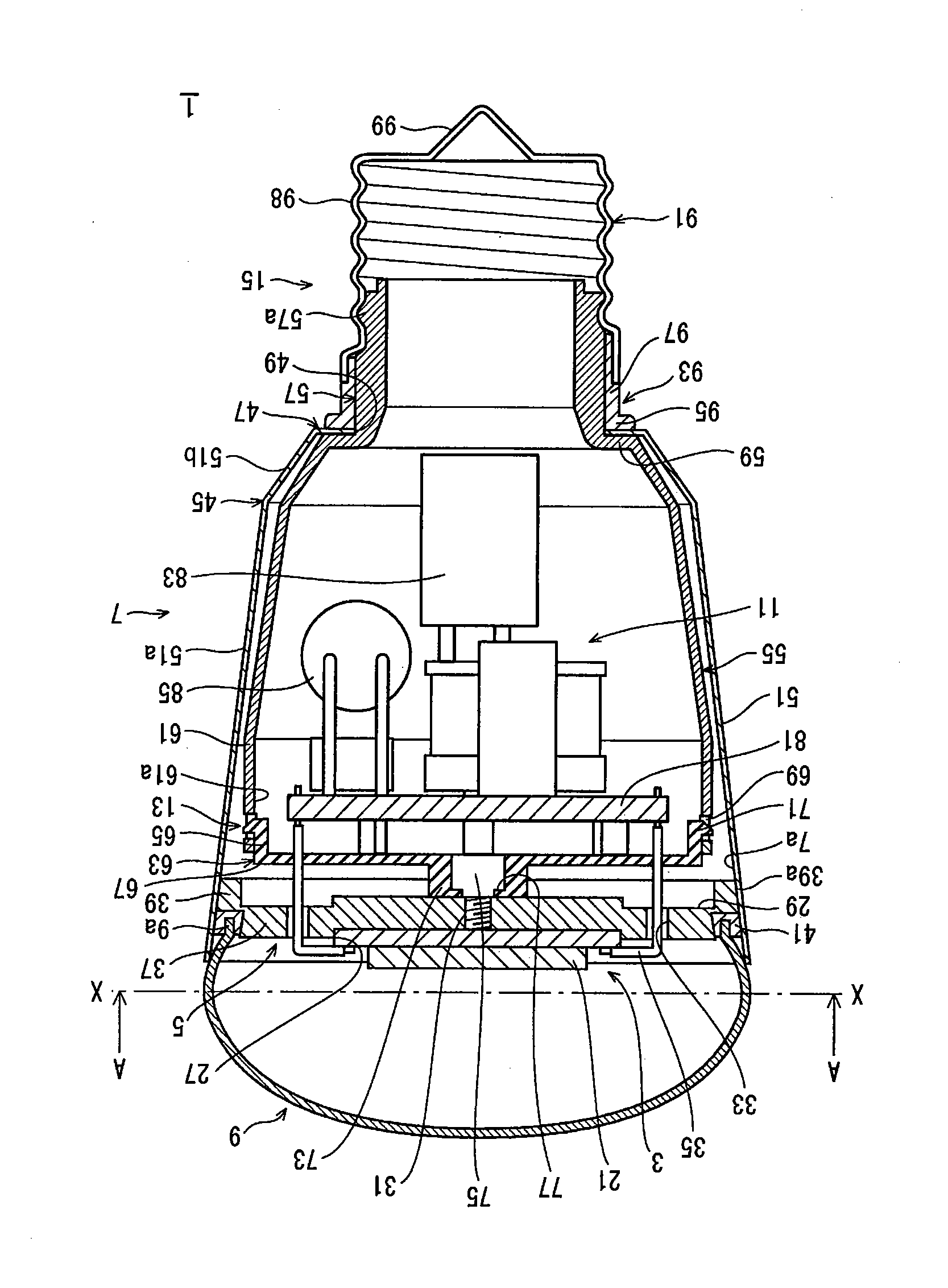
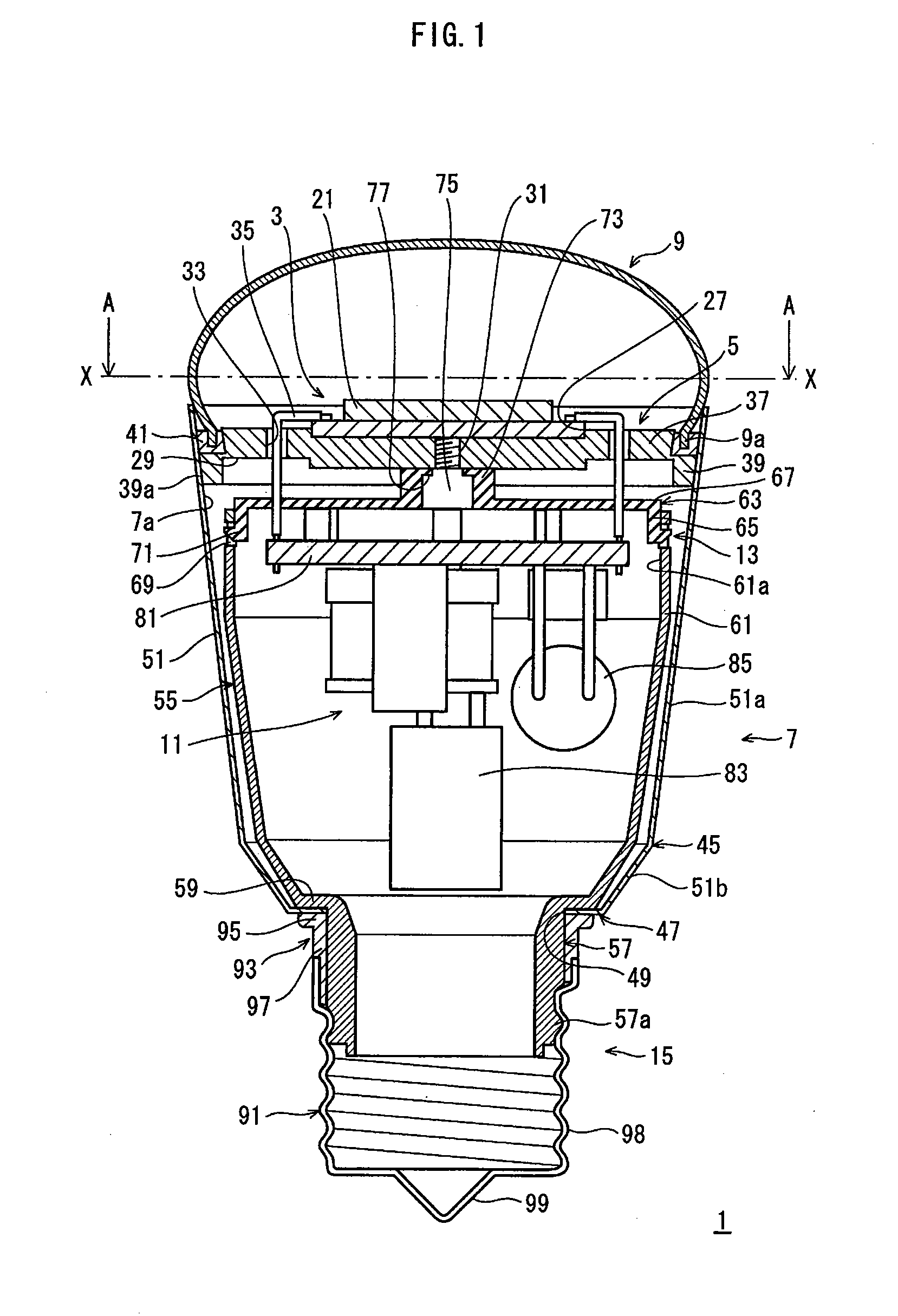
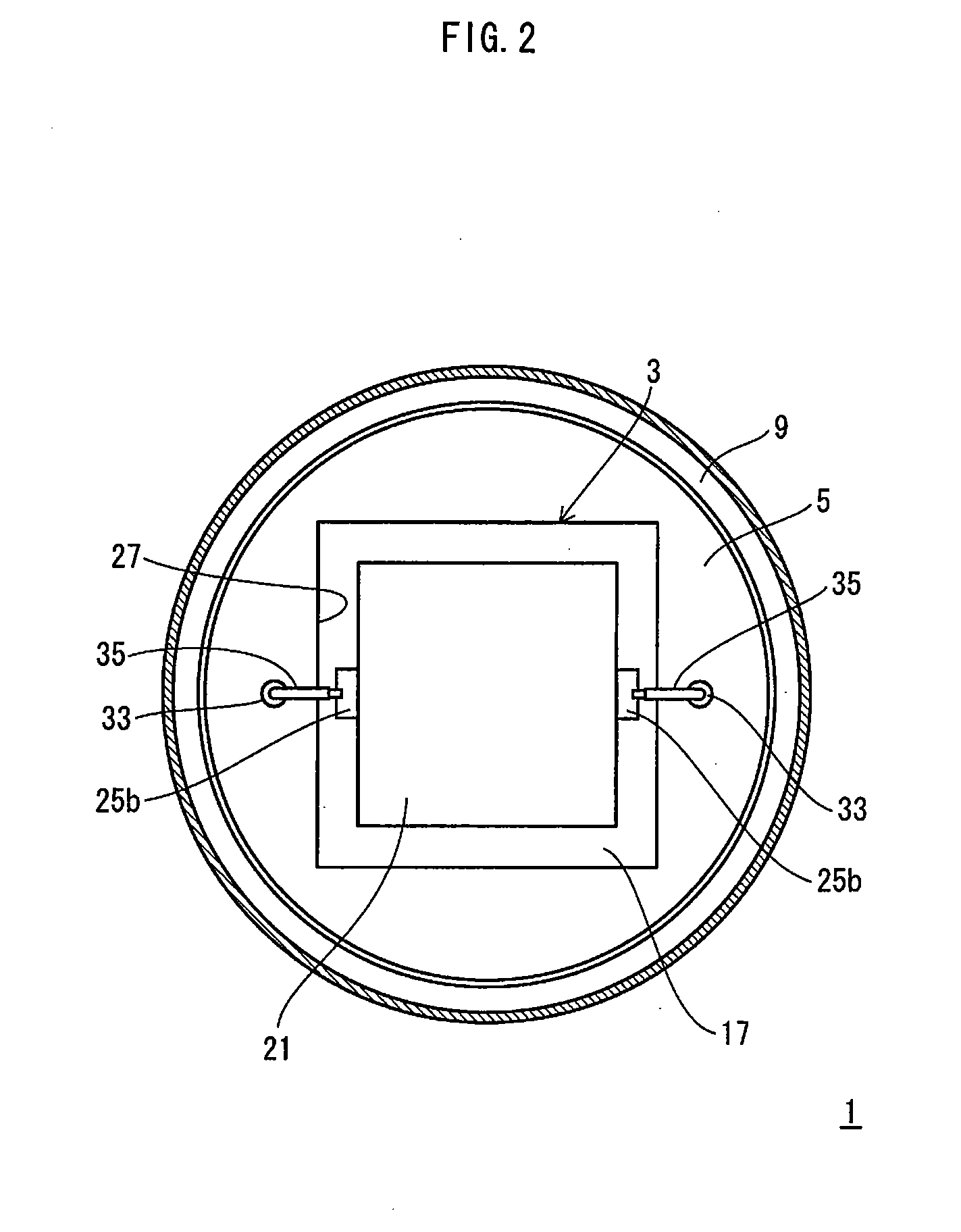
[0036]FIG. 1 is a longitudinal cross-sectional view of a bulb-type lamp pertaining to First Embodiment. FIG. 2 shows a cross section taken along a line X-X of FIG. 1 when viewed in a direction of arrows A.

[0037]As shown in FIG. 1, a bulb-type lamp (hereinafter referred to as an “LED light bulb”) 1 is composed of (i) an LED module 3 comprising a plurality of LEDs as a light source, (ii) a mount member 5 on which the LED module 3 is mounted, (iii) a case 7, to a first end portion thereof the mount member 5 is attached, (iv) a globe 9 that covers the LED module 3, (v) a lighting circuit 11 that lights the LEDs (causes the LEDs to emit light), (vi) a circuit holder 13 positioned inside the case 7, with the lighting circuit 11 disposed inside the circuit holder 13, and (vii) a base member 15 attached to a second end portion of the case 7. The LEDs, the LED module 3, the case 7, and the lighting circuit 11 correspond to the “at least one light emitting element”, “light emittin...

embodiment examples

2. Embodiment Examples

[0085]The LED light bulb 1 pertaining to First Embodiment may be implemented as, for example, a 60-watt incandescent light bulb or a 40-watt incandescent light bulb. Hereinafter, an LED light bulb equivalent to a 60-watt incandescent light bulb is referred to as a “60-watt equivalent”, and an LED light bulb equivalent to a 40-watt incandescent light bulb is referred to as a “40-watt equivalent”.

(1) LED Module 3

[0086]By way of example, the substrate body 23 of the substrate 17 may be made of a resin material, a ceramic material, or the like. It is preferable that the substrate body 23 be made of a material having high thermal conductivity. The substrate body 23 has a thickness of 1 (mm).

[0087]The substrate body 23 has a square shape in planar view. In the 40-watt equivalent, each side of the square substrate body 23 has a length of 21 (mm). In the 60-watt equivalent, each side of the square substrate body 23 has a length of 26 (mm). Therefore, a contact area S2 ...

second embodiment

[0173]In Second Embodiment, the case has been anodized to improve its emissivity. This way, the case can be made with a thin wall thickness while preserving the heat dissipation properties.

[0174]FIG. 10 is a longitudinal cross-sectional view showing a general structure of an LED light bulb 201 pertaining to Second Embodiment of the present invention.

[0175]The LED light bulb 201 includes, as major structural components, a case 203, an LED module 205, a base member 207, and a lighting circuit 209. The case 203 has a cylindrical shape. The LED module 205 is attached to a first end portion of the case 203 in a longitudinal direction of the case 203. The base member 207 is attached to a second end portion of the case 203. The lighting circuit 209 is positioned inside the case 203.

[0176]The case 203 is made up of a first tapered portion 203a, a second tapered portion 203b and a bottom portion (bent portion) 203c. A diameter of the first tapered portion 203a decreases from a first end towa...


PUM


Abstract

Provided is a bulb-type lamp including a lightweight housing with great handleability. An LED light bulb (1) comprises: an LED module (3) on which LEDs are mounted; a cylindrically-shaped case (7) having openings at both ends, which are first and second ends; a mount member (5) on a front surface of which the LED module (3) is mounted, the mount member (5) closing a corresponding one of the openings of the case (7) by being in contact with an inner circumferential surface of the first end of the case (7); a base member (91) attached to the second end of the case (7); and a lighting circuit (11) that is disposed inside the case (7). A wall thickness of the case (7) is in a range of 200 μm to 500 μm inclusive, and the wall thickness of at least one portion of the case (7) decreases from the first end toward the second end of the case (7).

Description

TECHNICAL FIELD[0001]The present invention relates to a bulb-type lamp that uses light emitting elements and can replace another light bulb, and to a lighting device.BACKGROUND ART[0002]In recent years, for the purpose of energy conservation and prevention of further global warming, research and development of lighting devices employing light emitting diodes (LEDs) have been conducted in the field of lighting. LEDs can achieve higher energy efficiency than conventional incandescent light bulbs and the like.[0003]For example, a conventional incandescent light bulb offers an energy efficiency of tens of (lm / W). In contrast, LEDs, when used as a light source, achieve higher energy efficiency—more specifically, an energy efficiency of 100 (lm / W) or higher (hereinafter, a bulb-type lamp equipped with the LEDs and designed to replace another light bulb is referred to as an “LED light bulb”).[0004]Patent Literatures 1 and 2, etc. introduce an LED light bulb that can replace a conventional ...

Claims


Application Information

Patent Timeline
Patent Type & Authority Applications(United States)
IPC IPC(8): H01J13/46
CPCF21K9/135F21K9/1355F21S8/026F21V3/00F21V29/70F21V23/009F21Y2101/02F21V23/002F21V29/507F21V23/006F21K9/23F21K9/232F21K9/238F21Y2115/10
Inventor TAKAHASI, KENZITOMIYOSHI, YASUSHIGESHIDA, SATOSHISETOMOTO, TATSUMITANIUCH, AKIRAUEMOTO, TAKAARINAGAI, HIDEO
Owner PANASONIC INTELLECTUAL PROPERTY MANAGEMENT CO LTD
Why Eureka
Eureka Blog
Learn More