
Agricultural boom structure

a boom structure and agricultural technology, applied in the field of boom structures, can solve the problems of large inertial loads, extreme torsional stresses on the boom structure, and easy and repeatable manufacturability and structural soundness and stiffness, etc., and achieve the effect of improving the boom structur

Inactive Publication Date: 2005-11-22
DEERE & CO
View PDF15 Cites 28 Cited by
  • Summary
  • Abstract
  • Description
  • Claims
  • Application Information

AI Technical Summary

Benefits of technology

[0006]It is therefore an object of the present invention to provide an improved boom structure. It is another object to provide such a structure which overcomes one or more of the aforementioned problems.
[0007]It is another object of the present invention to provide an improved boom structure which is particularly useful for use with agricultural implements such as self-propelled field sprayers. It is another object to provide such a structure which relatively light and yet is strong and has desired stiffness. It is a further object to provide such a structure which is easy and inexpensive to manufacture.
[0008]It is still another object of the invention to provide an improved boom structure which reduces the cost of tooling, manufacturing and production. It is a further object to provide such a structure which reduces the amount of fixturing required during manufacture and reduces or eliminates problems associated with cut end joint tolerances and tube to tube end connections. It is another object to provide such a structure having tube support members with optimized weight and strength.
[0009]It is yet another object of the present invention to provide an improved boom structure which facilitates better nozzle or dispenser and supply tube plumbing placement than at least most conventional boom structures. It is a further object to provide such a structure which is wider at the top than at the bottom and which has improved strength in the fore-and-aft direction. It is another object to provide such a structure which is particularly advantageous for an over-top wing fold configuration and which overcomes design difficulties in boom tilt and fold construction caused by boom design configurations which transfer main loading towards the top of the boom.
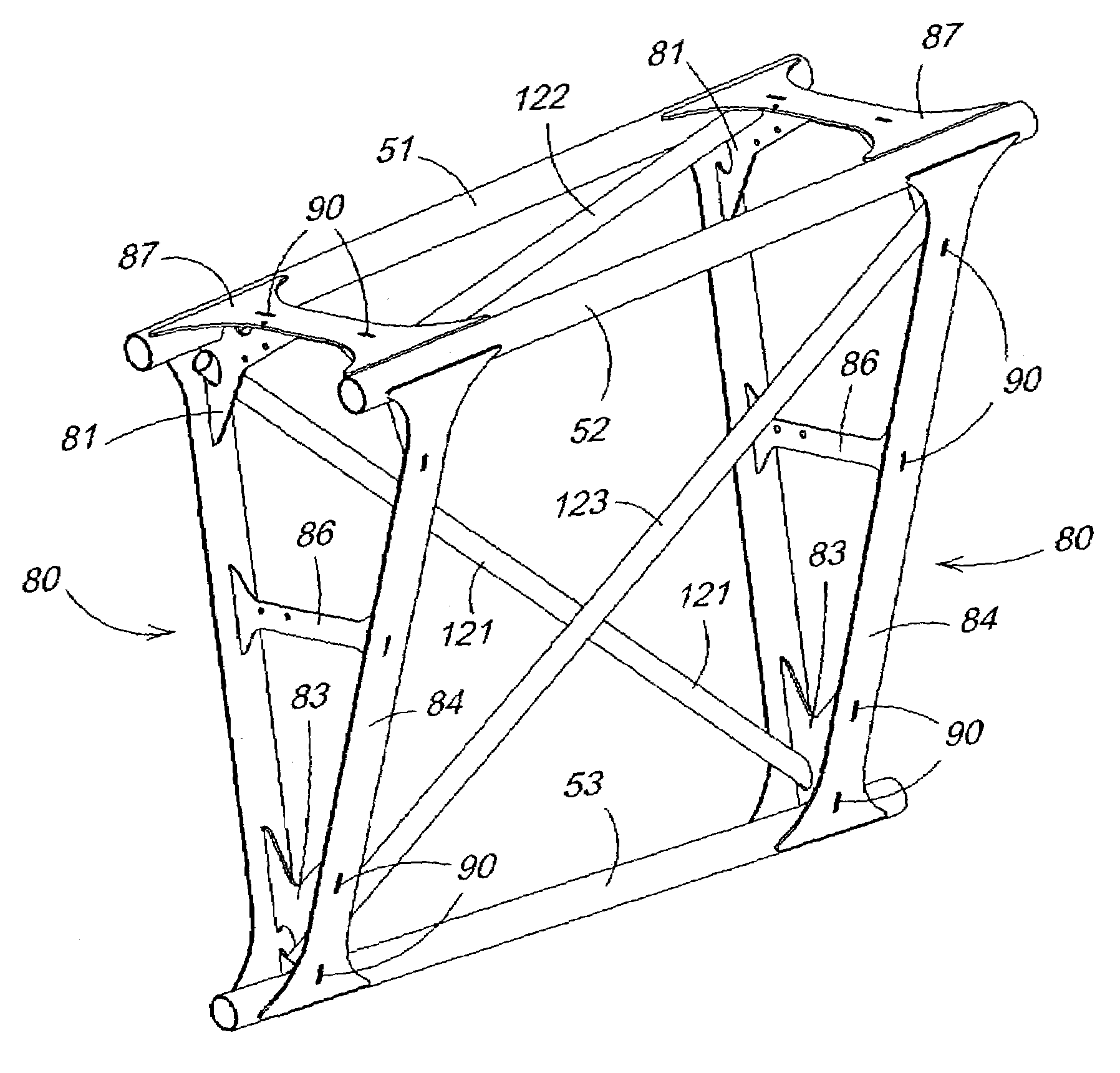
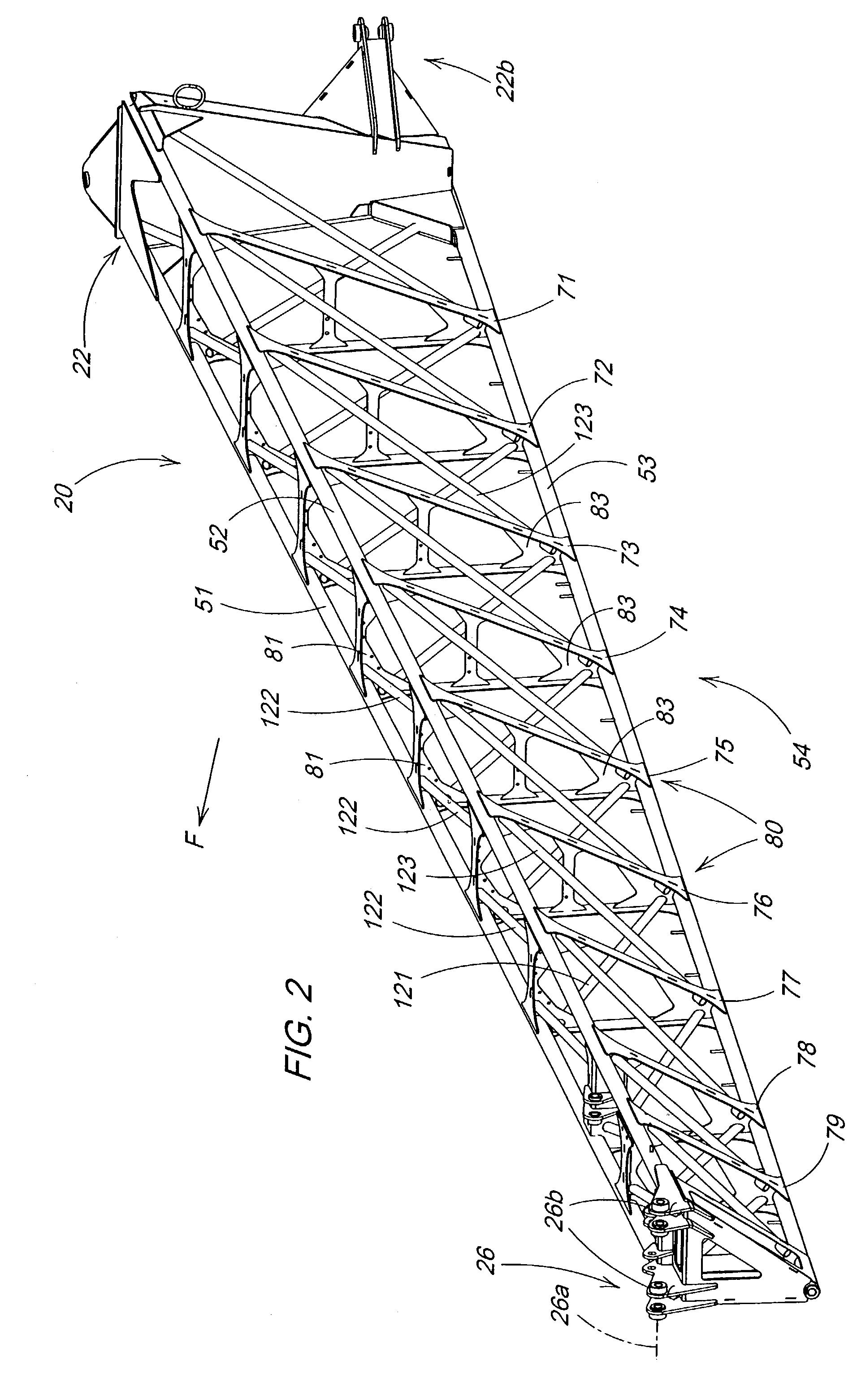
[0010]An easily manufactured boom construction particularly useful for large agricultural folding booms includes a plurality of main tube support sections fabricated from plate material of differing thickness and section dependent on the load to be carried by the material. Thicker, higher strength, or higher grade material is used only in high stress areas so that cost and weight are reduced and weight distribution and strength are improved. The material can be laser cut from steel stock and fitted together with the use of tab-slot locators to create a section substantially more precise than is available using saw-cut pieces. The tube support sections include apertured or slotted areas which provide a preliminary snap-fit of the main tubes to significantly reduce need for additional fixturing so that tooling and manufacturing costs are reduced when compared with at least most conventional boom constructions. The opposite ends of diagonal tubes pass through apertures in the fabricated support sections, rather than mate against the surface of the plates. Therefore the diagonal tubes can be precisely located without the need for expensive and complicated weld fixtures. Diagonal tube length and cut end angle tolerances can be substantially greater than possible with structures which use tube end to flat plate mating surfaces or direct tube end to tube end connections. Since the tube ends actually pass through the support sections, each end can be welded on opposite sides of the sections at conveniently accessed locations. By eliminating most or all tube-to-tube connections and connections wherein a cut end edge has to be precisely placed against a planar surface, welds can be made more quickly, easily and reliably than with at least most previously available conventional boom constructions. By making diagonal tube connections at adjacent support sections, welds at intermediate locations on the diagonal tubes are eliminated.
[0011]In the embodiment shown, the cross section of the boom is in the shape of an inverted right triangle with the base of the triangle at an uppermost portion of the boom. The apex of the triangular cross section is located at a lowermost portion of the boom, and the forwardly facing portion of the boom lies generally in an upright plane. The inverted construction provides improved nozzle and plumbing, much of which can be outside the boom cross section, and better facilitates over-top folding of a boom section compared to most previous boom designs. A unique torque-tube inner hinge design helps facilitate the inverted section and permits the boom fold cylinder and tilt pivot structure to be located near the bottom of the boom with the tilt cylinder near the top of the boom to avoid spray pattern overlaps or gaps with boom tilting. The wider upper base of the triangular cross section improves boom strength and stiffness and allows steel to be utilized throughout the boom if desired rather than more expensive, lighter materials which often increase joint fabrication difficulties. An outer wing over-top fold configuration allows for the maximum depth dimension of the wing structure and maximized strength of the structure in the fore-aft direction.

Problems solved by technology

As boom size, weight and operating speed increase, large inertial loads are encountered.
Building a large boom with reduced weight, easy and repeatable manufacturability and structural soundness and stiffness has become an increasing problem.
Horizontal folding reduces fold height requirements but results in extreme torsional stresses on the boom structure.
For horizontal folding, the boom depth dimension is usually minimized, which results in reducing the boom strength and stiffness in the fore-and-aft direction.
Over-top folding relieves the torsional stress but can result in unacceptable fold heights with large booms.
Such structural designs that are wider at the bottom than at the top often interfere with desired spray nozzle positioning.
Spray nozzle spacing options are limited or operators have to offset certain nozzles from main plumbing line, and uneven spray patterns often result.
Attempts at providing alternate configurations have met with difficulties, particularly if in the alternate configuration loading is transferred towards the top of the boom.
This separation and overlap cause significant spray pattern problems.
Therefore, providing such alternate boom configurations have met with significant design difficulties caused by the load transfers and tilt and fold requirements.
Large booms with tubular designs are often very difficult to manufacture.
Where tube-to-tube connections are required, such tolerances increase the difficulty and cost of welding tube ends together, and the structural integrity of such tube end weld connections is less than optimum.
In addition, conventional tubular boom construction methods require a complex and expensive boom weldment fixture.

Method used


Image

  • Agricultural boom structure
  • Agricultural boom structure
  • Agricultural boom structure

Examples


Embodiment Construction

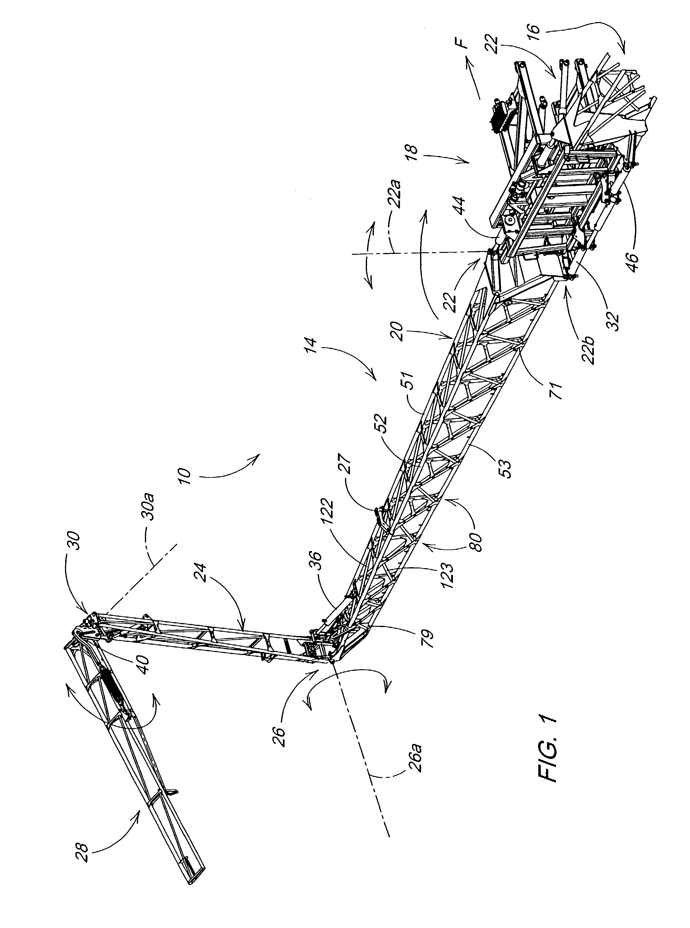
[0025]Referring now to FIG. 1, therein is shown a portion of an agricultural implement 10 such as a large field sprayer adapter for forward movement (F) over a field to be sprayed. The implement 10 includes right- and left-hand boom assemblies 14 and 16 supported on a vehicle or trailer (not shown) by a lift frame support or centerframe assembly 18. The boom assemblies 14 and 16 are similar in construction and, as shown, include an inner boom section 20 connected to the support assembly 18 for pivoting about an upright axis 22a by a structural hinge 22 for movement between an extended field working position (shown) and a forwardly folded position wherein the section 20 extends forwardly from the support assembly 18. An intermediate boom section 24 is connected by hinge structure 26 to the outer end of the section 20 for pivoting between an outwardly extended field working position and a transport position overlying the section 20 against a stop 27 on the top of the section 20. An ou...


PUM


Abstract

An easily manufactured large boom construction includes a plurality of main tube support sections fabricated from plate material of differing material thickness, grade and section dependent on load. The tube support sections include apertured areas which provide a preliminary snap-fit of the main tubes to significantly reduce need for additional fixturing. The opposite ends of diagonal tubes pass through apertures in the fabricated support sections for accurate tube location without complicated weld fixtures or precise tube length and cut end angle tolerances. The tubes are welded on opposite sides of the sections to eliminate need for tube-to-tube connections or connections wherein a cut end edge has to be precisely placed against a planar surface. An inverted right triangle boom cross section with wing over-top fold configuration ability provides strength, stiffness and infinite nozzle placement possibilities.

Description

FIELD OF THE INVENTION[0001]The present invention relates generally to boom structure for agricultural implements such as field sprayers.BACKGROUND OF THE INVENTION[0002]The desire to increase productivity and reduce the number of passes over a field, implements with folding booms such as field sprayers have been designed for increased working widths and increased operating speeds. Booms which fold out to define a working width of up to 120 feet or more are now available. As boom size, weight and operating speed increase, large inertial loads are encountered. Building a large boom with reduced weight, easy and repeatable manufacturability and structural soundness and stiffness has become an increasing problem.[0003]The wide booms must fold to achieve a narrowed transport width. Horizontal folding reduces fold height requirements but results in extreme torsional stresses on the boom structure. For horizontal folding, the boom depth dimension is usually minimized, which results in red...

Claims


Application Information

Patent Timeline
IPC IPC(8): A01M7/00
CPCA01M7/0071A01M7/0075
Inventor WUBBEN, THOMAS MARKKLEMME, KENT ALVINSTEPHENS, BRENDEN LEWSINK, III, HENRY CLIFTONTHOMAS, CLARK STEELBERBERICH, MICAH JOEL
Owner DEERE & CO
Learn More