Electrical power tool having vibration control mechanism

a technology of electric power tools and vibration control, which is applied in the field of electric power tools, can solve the problems of reduced visibility, increased size of electrical power tools, and high cost, and achieves the effects of increasing the number of parts, high production cost, and high cos

Inactive Publication Date: 2009-12-29
KOKI HLDG CO LTD
View PDF13 Cites 24 Cited by
  • Summary
  • Abstract
  • Description
  • Claims
  • Application Information

AI Technical Summary

Benefits of technology

[0009]However, the electrical power tool described above requires the cylinder with high production cost and a large number of parts, thereby leading high cost. Further, two vibration control housings need to provide on the both sides of the impact housing for canceling the rotational moments acting on the electrical power tool, thereby increasing the number of parts.
[0010]Further, the vibration control housings are provided on the both sides of the impact housing, thereby leading to an increased size in the electrical power tool, reduced visibility and reduced operability of the electrical power tool.
[0011]In view of the foregoing, it is an object of the present invention to provide an electrical power tool that is capable of efficiently reducing the vibration resulting from the striking member and that does not lead to an increased size and to reduced operability of the electrical power tool.

Problems solved by technology

However, the electrical power tool described above requires the cylinder with high production cost and a large number of parts, thereby leading high cost.
Further, the vibration control housings are provided on the both sides of the impact housing, thereby leading to an increased size in the electrical power tool, reduced visibility and reduced operability of the electrical power tool.

Method used


Image

  • Electrical power tool having vibration control mechanism
  • Electrical power tool having vibration control mechanism
  • Electrical power tool having vibration control mechanism

Examples


first embodiment

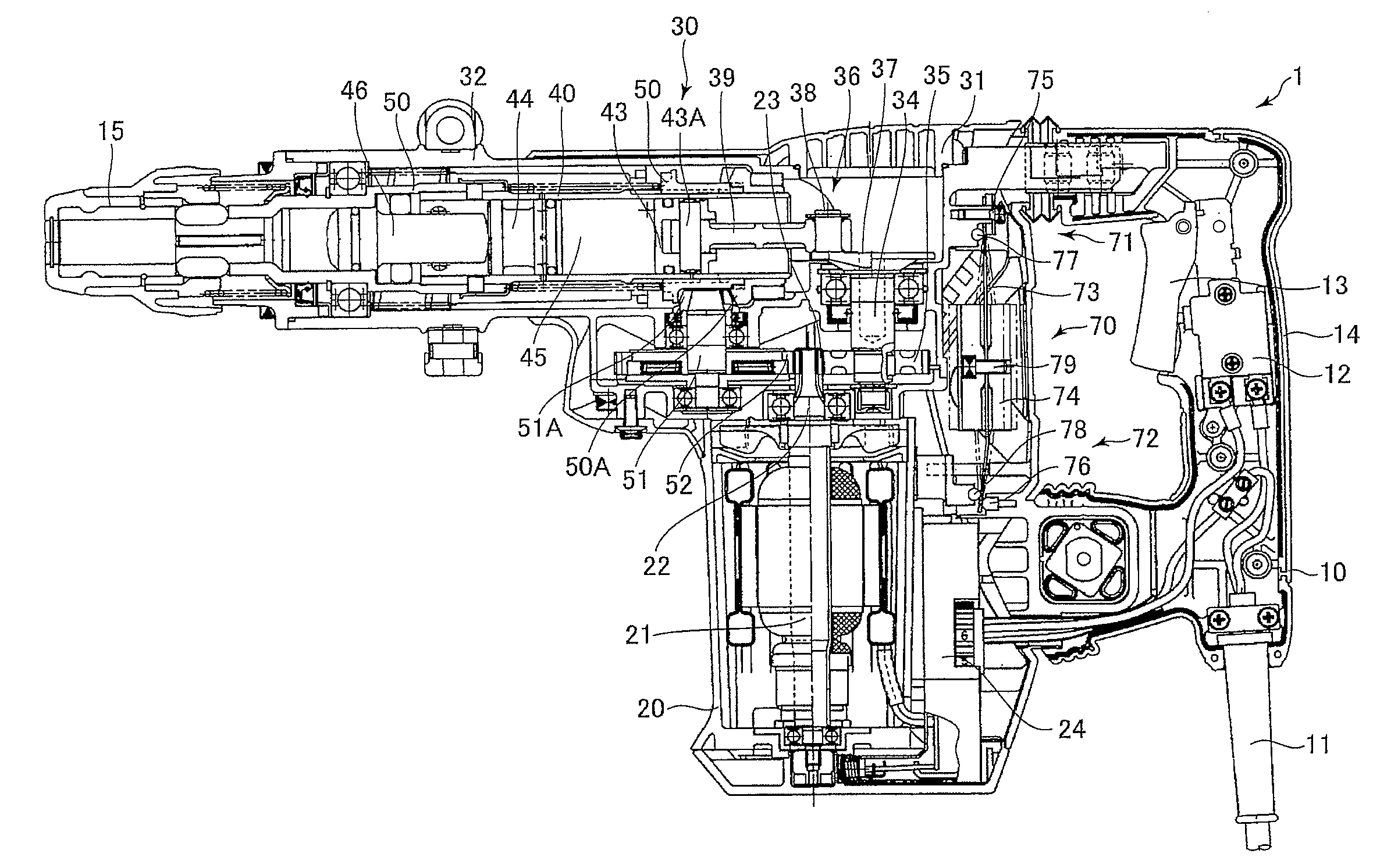
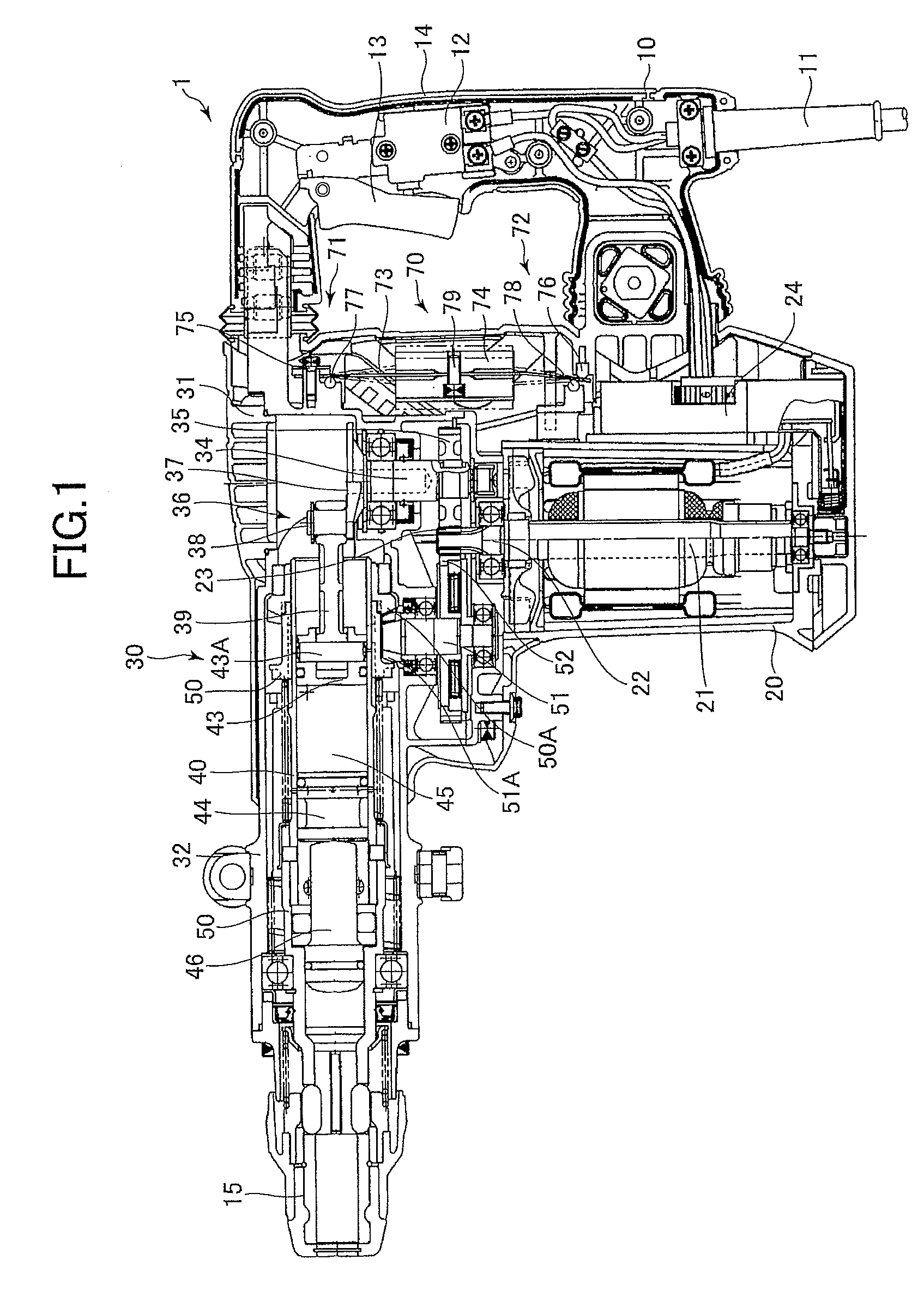
[0039]Next, the operation of the impact tool 1 will be described. The working tool (not shown) is pressed against a workpiece (not shown) with the handle 10 gripped by the user. Next, the trigger 12 is pulled to supply power to and rotate the electrical motor 21. This rotation driving force is transmitted to the crank shaft 34 by way of the pinion gear 23 and the first gear 35. The rotation of the crank shaft 34 is converted into reciprocation motion of the piston 43 in the cylinder 40 by the motion converter mechanism 36 (the crank weight 37, the crank pin 38, and the connecting rod 39). The reciprocation motion of the piston 43 leads to repeated increments and decrements of the pressure of the air in the air chamber 45, thereby causing a reciprocation motion of the striking member 44. The striking member 44 moves forward and collides with the rear end of the intermediate member 46, thereby applying an impact force to the working tool (not shown).

[0040]Also, the rotation driving f...

second embodiment

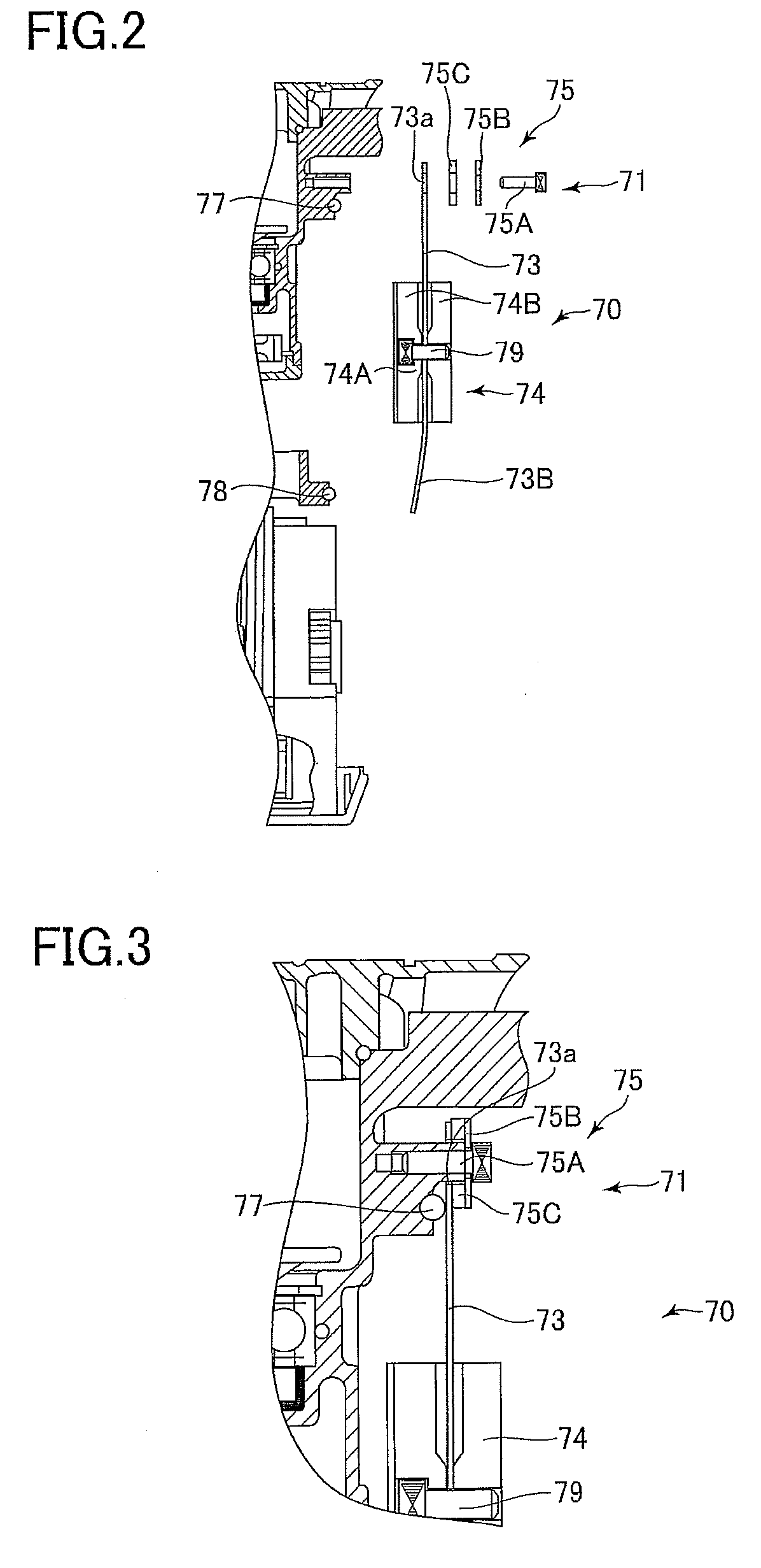
[0049]A counterweight mechanism 170 has a weight-supporting member 173. The weight-supporting member 173 includes a first connecting part 173B and a second connecting part 173C positioned one on each end of the weight-supporting member 173, and an elastically deforming part 173D connecting the first and second connecting parts 173B and 173C. The elastically deforming part 173D includes first and second deforming parts 173D1 and 173D2 and a weight-mounting part 173D3. The first and second deforming parts 173D1 and 173D2 have a thickness formed partially thinner than the first and second connecting parts 173B and 173C and the weight-mounting part 173D3. Accordingly, each cross-sectional area of the first and second deforming parts 173D1 and 173D2 is smaller than the cross-sectional area in a portion where the first connecting part 173B contacts the first inside supporting member 77, the cross-sectional area in a portion where the second connecting part 173C contacts the second inside...

third embodiment

[0051]Next, an electrical power tool according to the present invention will be described while referring to FIGS. 7 and 8. The electrical power tool of the present invention is applied to an impact tool 201. The impact tool 201 includes a casing having the handle 10, the motor housing 20, a weight housing 60, and a gear housing 80.

[0052]The power cable 11 is attached to the handle 10. The handle 10 houses the switch mechanism 12. The trigger 13 that can be manipulated by the user is mechanically connected to the switch mechanism 12. The switch mechanism 12 is connected to an external power source (not shown) through power cable 11. By operating the trigger 13, the switch mechanism 12 can be connected to and disconnected from the external power source.

[0053]The motor housing 20 is provided on the front side of the handle 10. The handle 10 and the motor housing 20 are formed integrally from plastic. The electrical motor 21 is accommodated in the motor housing 20. The electrical motor...


PUM

PropertyMeasurementUnit
stressaaaaaaaaaa
areaaaaaaaaaaa
elastic deformationaaaaaaaaaa

Abstract

An electrical power tool includes a housing, an electrical motor, a motion conversion mechanism, a weight-supporting member, a counterweight, and a first supporting member and a second supporting member. The first supporting member and the second supporting member are each provided on the housing for supporting the weight-supporting member to the housing. The weight-supporting member has a first connecting part and a second connecting part supported by the first supporting member and the second supporting member, respectively; and an elastically deforming part. The elastically deforming part is positioned between the first connecting part and the second connecting part and has a mounting part for mounting the counterweight. The elastically deforming part includes a portion having a smaller cross-sectional area than each cross-sectional area of the first connecting part and the second connecting part.

Description

BACKGROUND OF THE INVENTION[0001]1. Field of the Invention[0002]The present invention relates to an electrical power tool and more specifically, to an electrical power tool having a vibration control mechanism.[0003]2. Description of the Related Art[0004]Conventionally, electrical power tools having vibration control mechanisms have been proposed. For example, Japanese Patent Application Publication No. 2004-299036 discloses an electrical power tool including a casing that has a handle, a motor housing, and a gear housing connected with one another. An electrical motor is accommodated in the motor housing. The gear housing has a motion conversion housing, a vibration control housing, and an impact housing. A motion conversion mechanism that converts a rotation motion of the electrical motor into a reciprocation motion is provided in the motion conversion housing. A cylinder extending a direction perpendicular to the rotation axis of the electrical motor is provided in the impact hou...

Claims


Application Information

Patent Timeline
Patent Type & Authority Patents(United States)
IPC IPC(8): B25D11/00
CPCB25D17/24Y10T16/48B25D2250/381B25D2217/0092
Inventor SATO, SHINICHIRO
Owner KOKI HLDG CO LTD
Why Eureka
Try Eureka