Electrical connector box with customizable bus bar circuit assembly
a technology of electrical connectors and circuit assemblies, which is applied in the direction of printed circuits, electrical apparatus, coupling device connections, etc., can solve the problems of restricting the freedom with which wiring connection patterns can be designed, restricting the number of wires in the plug-in block, and restricting the circuit connection to the wires. , to achieve the effect of simplifying the wiring harness assembly process and easy to adapt changes
- Summary
- Abstract
- Description
- Claims
- Application Information
AI Technical Summary
Benefits of technology
Problems solved by technology
Method used
Image
Examples
case 14
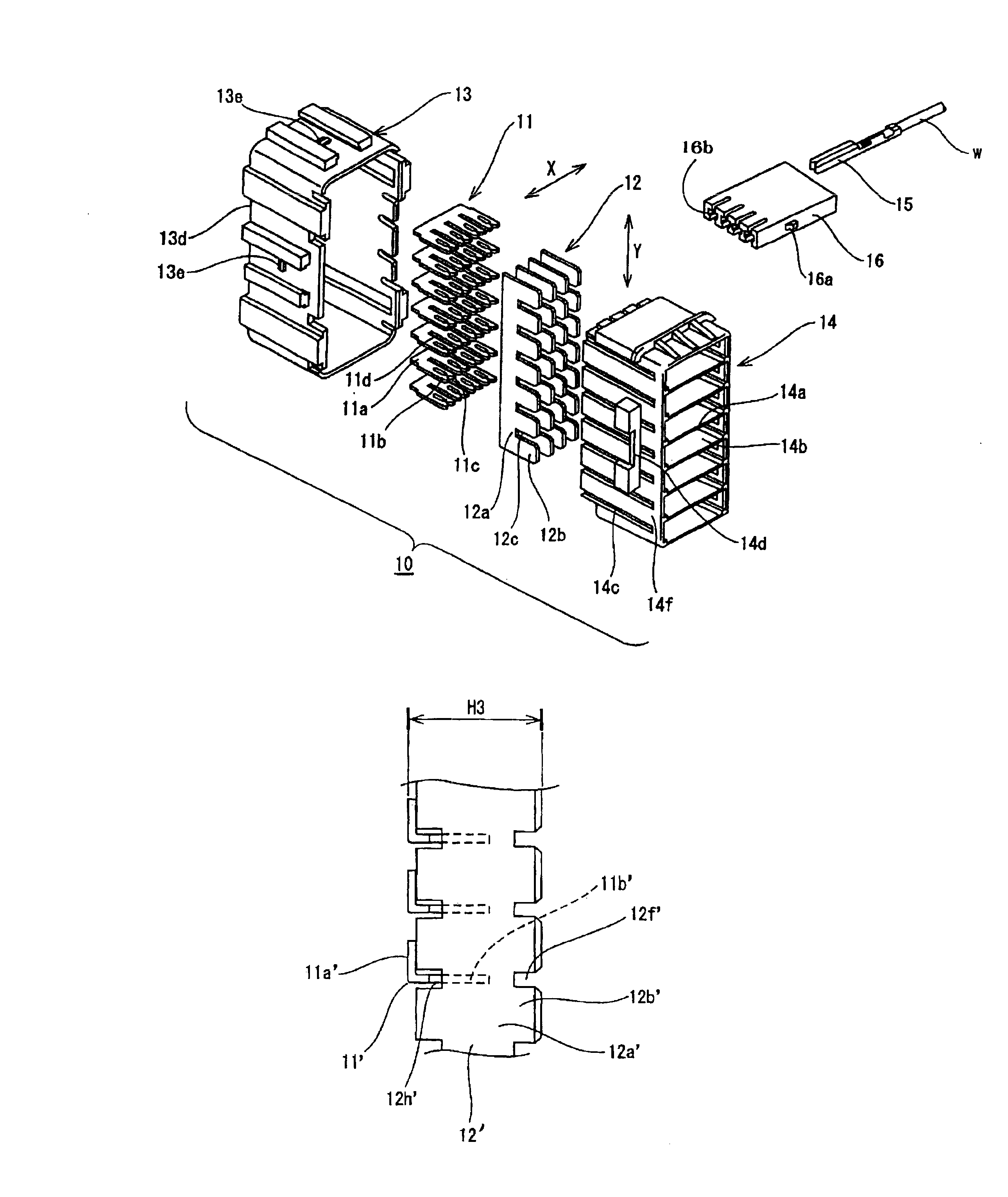
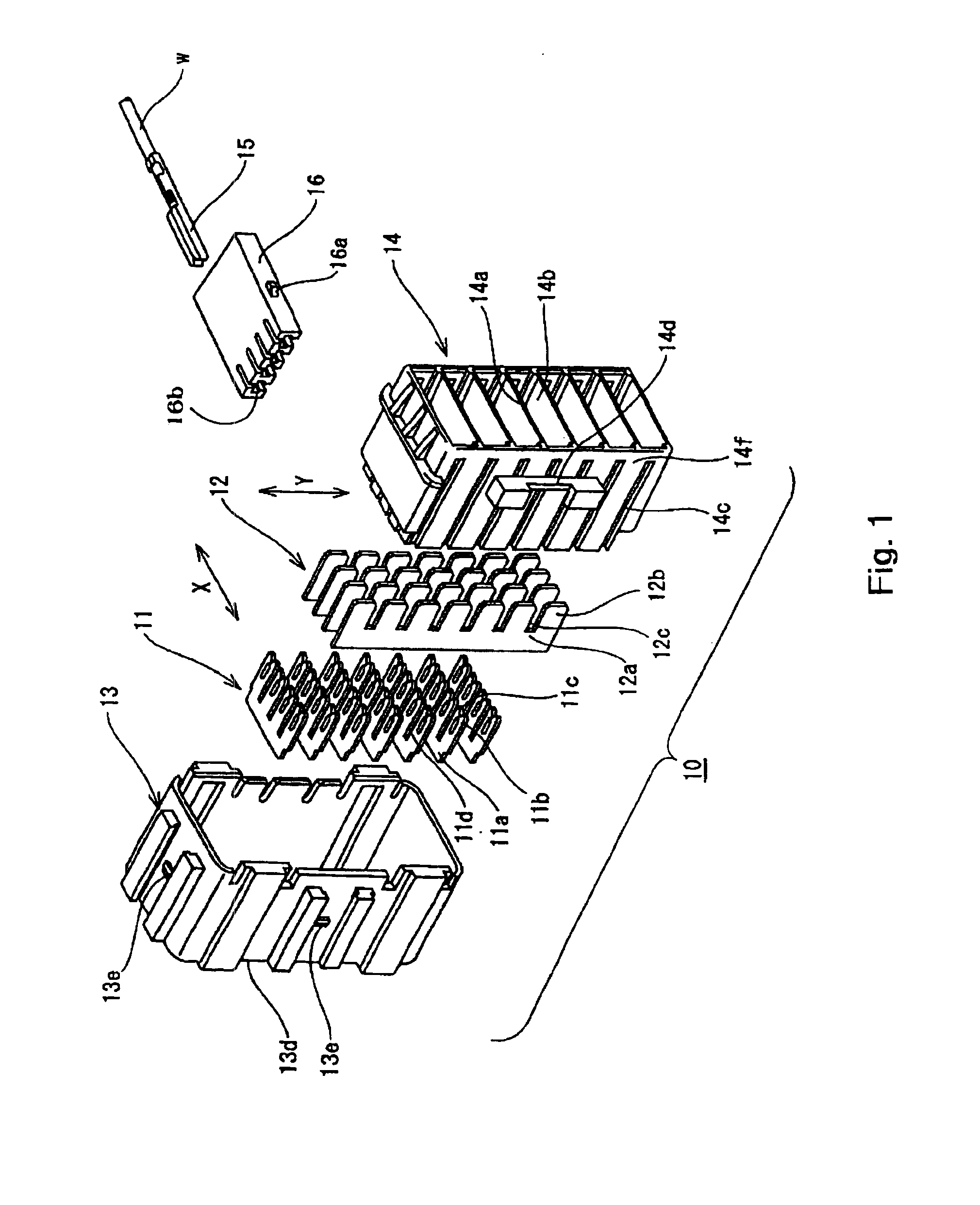
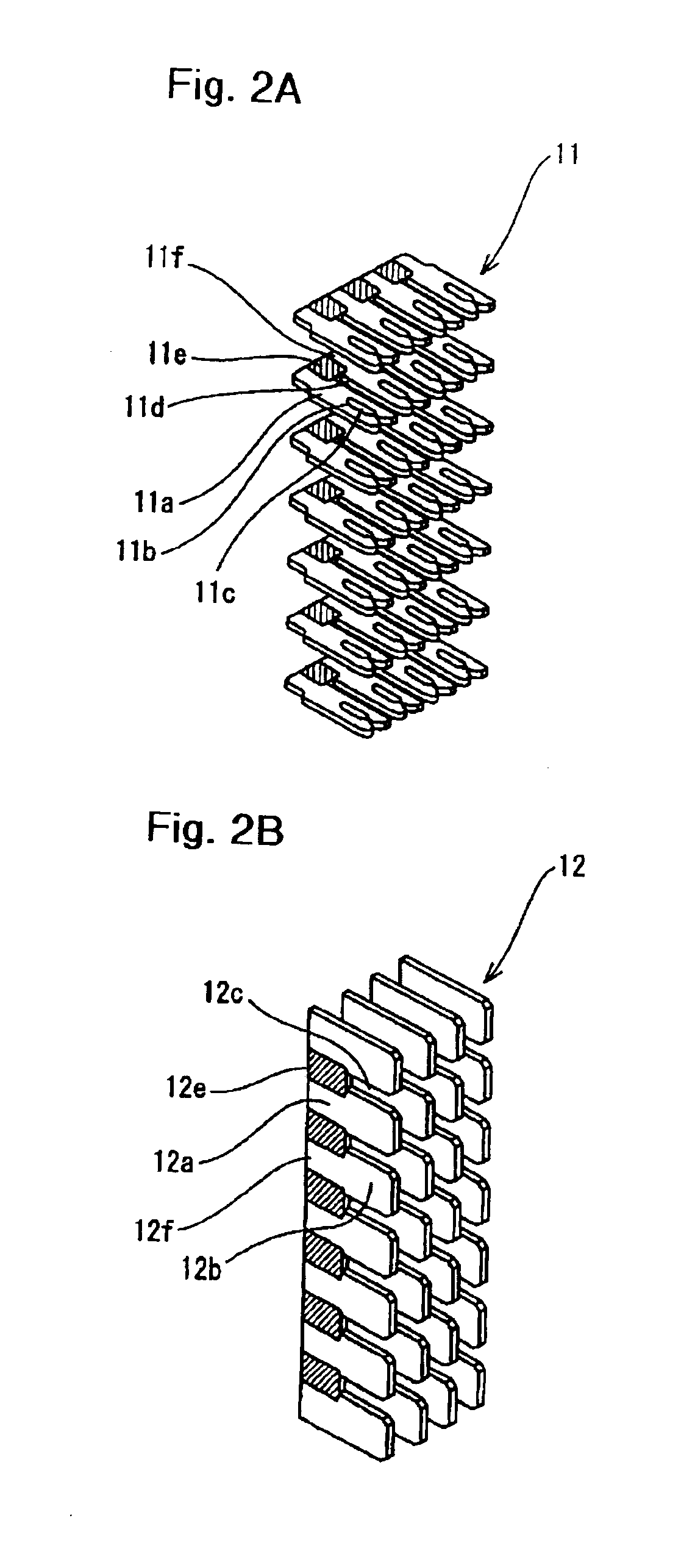
Upper case 14 is then inserted into lower case 13 and locked therein (i.e., the upper case is assembled over the lower case to form the case housing). At this point, second bus bar terminals 12b are aligned in parallel within each vertically aligned plug-in aperture 14b in upper case 14.
With connector box 10 assembled as described above, connector terminals 15, to which the ends of circuit connecting wires ‘w’ have been attached, are inserted and anchored within plug-in block 16. It is apparent to those skilled in the art that the circuit connecting wires need not be previously inserted within the same plug-in block 16.
Plug-in blocks 16 are then inserted and anchored within each connector plug-in aperture 14b. With plug-in blocks 16 thus installed to connector box 10, connector terminals 15 join to second terminals 12b, thus forming a connection between the wires in the required circuit connection pattern. While the illustrated embodiment shows female connector terminals 15 and male...
second embodiment
FIGS. 5, 6A and 6B illustrate the present invention. This second embodiment allows for connector box 10 to be made to a more compact size by reducing the distance, or profile (shown as dimension H2 in the figures) from the leading edge of first bus bar 11 at the attachment point in the lower case, to the edge of second bus bar 12 at the upper case side, when first and second bus bars 11 and 12 are assembled within lower case 13 and upper case 14 (i.e., when the bus bar assembly is inside the case housing).
Slots 12h′ are formed between connector bands 12a′ on second bus bar 12′ at locations thereon opposite to spaces 12f (i.e., between the vertically aligned plug-in block apertures) which are defined by adjacently located terminals 12b′. That is, as illustrated in FIG. 5, slots 12h′ are cut into the connector band opposite and adjacent to each second terminal 12b′.
First bus bar 11 is placed opposite slots 12h′ on second bus bar 12′ in a position where first bus bar pinch prongs 11b ...
PUM
 Abstract
Description
Claims
Application Information
 - R&D
- Intellectual Property
- Life Sciences
- Materials
- Tech Scout
- Unparalleled Data Quality
- Higher Quality Content
- 60% Fewer Hallucinations
Browse by: Latest US Patents, China's latest patents, Technical Efficacy Thesaurus, Application Domain, Technology Topic, Popular Technical Reports.
© 2025 PatSnap. All rights reserved.Legal|Privacy policy|Modern Slavery Act Transparency Statement|Sitemap|About US| Contact US: help@patsnap.com


