
Adjustable bed

a technology of adjustable beds and beds, applied in the field of adjustable beds, can solve the problems of heavy weight, robustness, mechanical complexity, and inability to provide an arrangement that is suitable, and achieve the effect of reducing the load of actuators

Active Publication Date: 2021-03-02
MOTUS MECHANICS LTD
View PDF134 Cites 1 Cited by
  • Summary
  • Abstract
  • Description
  • Claims
  • Application Information

AI Technical Summary

Benefits of technology

[0027]The above aspect of the invention provides a simple arrangement for adjustable beds of the aforementioned zero gravity type. Mutual engagement of the cam means and cam follower means is readily maintained in all adjustment configurations. This can reduce weight and cost in arrangements of adjustable furniture as less complex structures may be implemented. In particular the above aspect of the invention contemplates embodiments without complex and expensive multiple actuating elements. This aspect of the invention can achieve significant weight and cost advantages without compromising performance and durability. This is a particular consideration in the domestic furniture industry where manufacturing cost is often of critical importance to product success in the marketplace. A significant advantage of the above aspect of the present invention is that the profile of the bed, that is to say the depth dimension of the bed, can be minimized, and thereby a low profile adjustable bed can be realized with attendant storage and shipping cost advantages, particularly when compared with hitherto known designs, due to a smaller depth dimension of the part assembled bed and actuation system. In this respect it will be understood that the depth dimension for shipping purposes is the depth of the bed minus legs or other support means which are shipped unassembled. Thus the reduced depth dimension readily enables greater number of units to be shipped in a given space, such as an ISO container or the like.
[0028]Preferably, the cam means is associated with the frame and the cam follower means is associated with the movable support section. The present invention also contemplates embodiments with the opposite arrangement, that is to say where the cam means is associated with the movable support section and the cam follower means is associated with the frame. However, the former arrangement, as in the illustrated embodiments disclosed herein, has been found to provide for a compact and mechanically efficient actuation system for adjustable furniture, particularly adjustable beds.
[0034]In preferred embodiments, the floor standing frame comprises first and second spaced apart parallel side frame members. This provides for a robust construction and which is preferably in the form of a rectangular structural frame.
[0035]In preferred embodiments actuator means is arranged to apply the adjustment force substantially to the underside of the support section to which it is attached, for example the intermediate support section of the head end support section. In this way the actuator loads may be minimized by increasing the perpendicular distance between the pivot axis of the respective support sections and the point of application of actuator load.
[0037]In preferred embodiments, cam means and cam follower means are provided on both lateral sides of the frame such that the movable intermediate support section is supported on both sides thereof. Thus, the above aspect of the invention readily enables the weight of the bed, including the weight of the occupant(s) and actuation system, to be evenly distributed and supported by the load bearing structure of the bed, which structure may be integrated in such a way that the weight carried by the furniture is evenly supported by the frame. The arrangement of the cam and cam follower means readily enables the adjustable support sections to be moved in a coordinated manner about their respective pivot axis.

Problems solved by technology

The arrangement disclosed in US2002 / 0174487 may be considered heavy, robust and mechanically complex.
This structure, while suitable for hospital beds, does not readily provide an arrangement that is suitable for more lightly used applications such as domestic furniture, where other design considerations, such as weight and cost and mechanical simplicity, come into play.

Method used


Image

  • Adjustable bed
  • Adjustable bed
  • Adjustable bed

Examples


Embodiment Construction

[0052]Reference will now be made in detail to embodiments of the invention. Wherever possible, same or similar reference numerals are used in the drawings and the description to refer to the same or like parts or steps. The drawings are in simplified form and are not to precise scale. The word ‘couple’ and similar terms do not necessarily denote direct and immediate connections, but also include connections through intermediate elements or devices. For purposes of convenience and clarity only, directional (up / down, etc.) or motional (forward / back, etc.) terms may be used with respect to the drawings. These and similar directional terms should not be construed to limit the scope in any manner. It will also be understood that other embodiments may be utilized without departing from the scope of the present invention, and that the detailed description is not to be taken in a limiting sense, and that elements may be differently positioned, or otherwise noted as in the appended claims wi...


PUM


Abstract

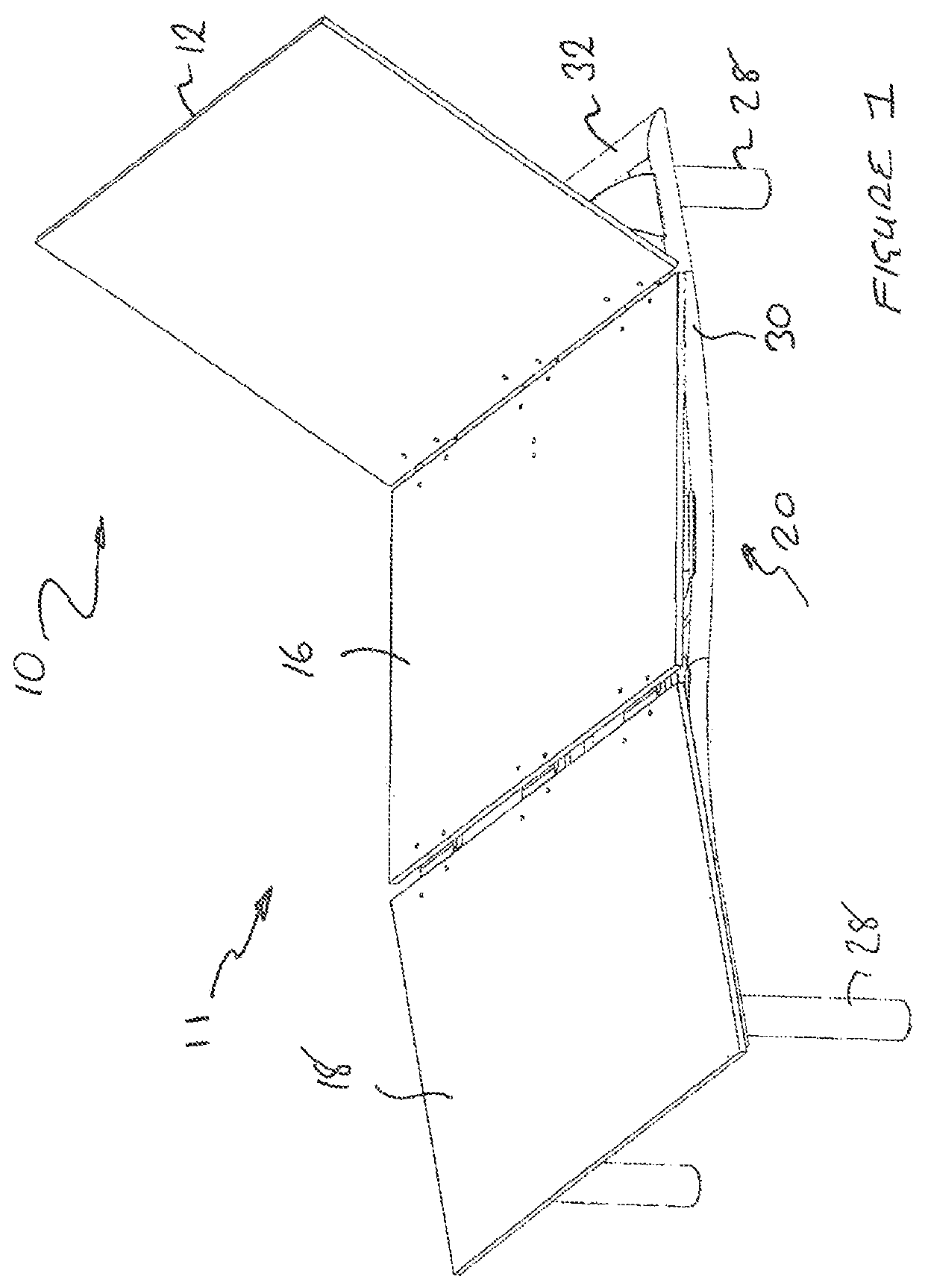
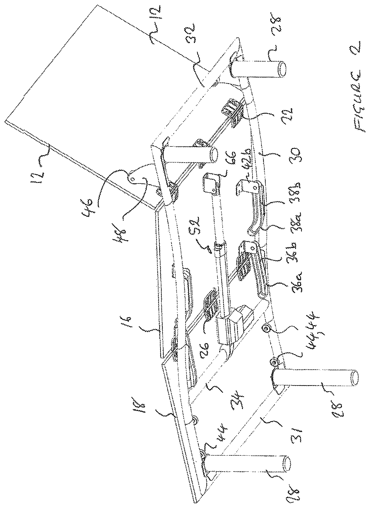
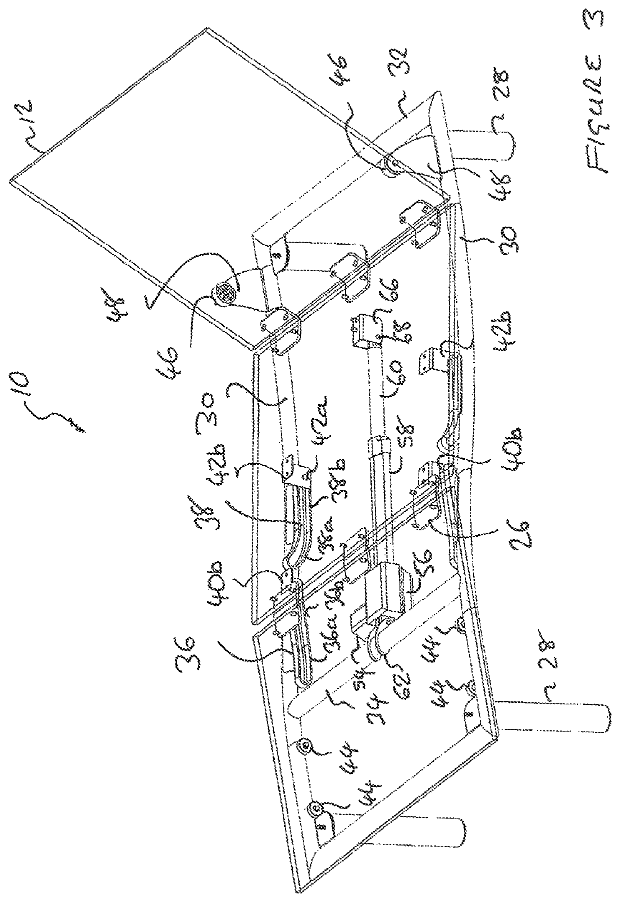
The invention concerns an adjustable bed (10) having zero wall clearance and zero gravity functionality. The bed comprises a frame (20) and an adjustable mattress support platform (11) having a plurality of articulated support sections (12, 16, 18) pivotally mounted with respect to one another for relative angular adjustment, and actuator means (52) for effecting coordinated movement of the support sections to reconfigure the bed, between a flat lowered configuration and a raised configuration for supporting an occupant in a zero gravity recumbent position. The actuator means comprises a single actuator, preferably a single linear actuator.

Description

CROSS REFERENCE TO RELATED APPLICATIONS[0001]This application relates to and claims priority as a § 371 national phase, from PCT / EP2016 / 055381 filed Mar. 11, 2016, the entire contents of which are incorporated herein by reference, which in turn claims priority from Great Britain Ser. No. 1504140.3 filed Mar. 11, 2015.FIGURE SELECTED FOR PUBLICATION[0002]FIG. 2BACKGROUND OF THE INVENTIONField of the Invention[0003]This invention relates to adjustable beds having adjustable mattress support sections which can be moved to adjust the configuration of the bed.Description of the Related Art[0004]Adjustable beds are known, for example, from US2002 / 0174487 which discloses a hospital bed having adjustable back and thigh sections. The hospital bed of US2002 / 0174487 comprises a frame having a pair of parallel and spaced apart first and second side frame members; a mattress support deck including an adjustable back section having first and second sides; a fixed seat section located adjacent to ...

Claims


Application Information

Patent Timeline
Patent Type & Authority Patents(United States)
IPC IPC(8): A47C20/12A47C20/08A47C20/04A47C19/02
CPCA47C20/12A47C19/025A47C20/041A47C20/08A61G7/015
Inventor BROWN, PAUL
Owner MOTUS MECHANICS LTD
Learn More