

Chain tension adjustment device of chain saw
- Summary
- Abstract
- Description
- Claims
- Application Information
AI Technical Summary
Benefits of technology
Problems solved by technology
Method used
Image

Examples
Embodiment Construction
[0024]Hereinbelow, an embodiment of the present invention will be described with reference to the drawings.
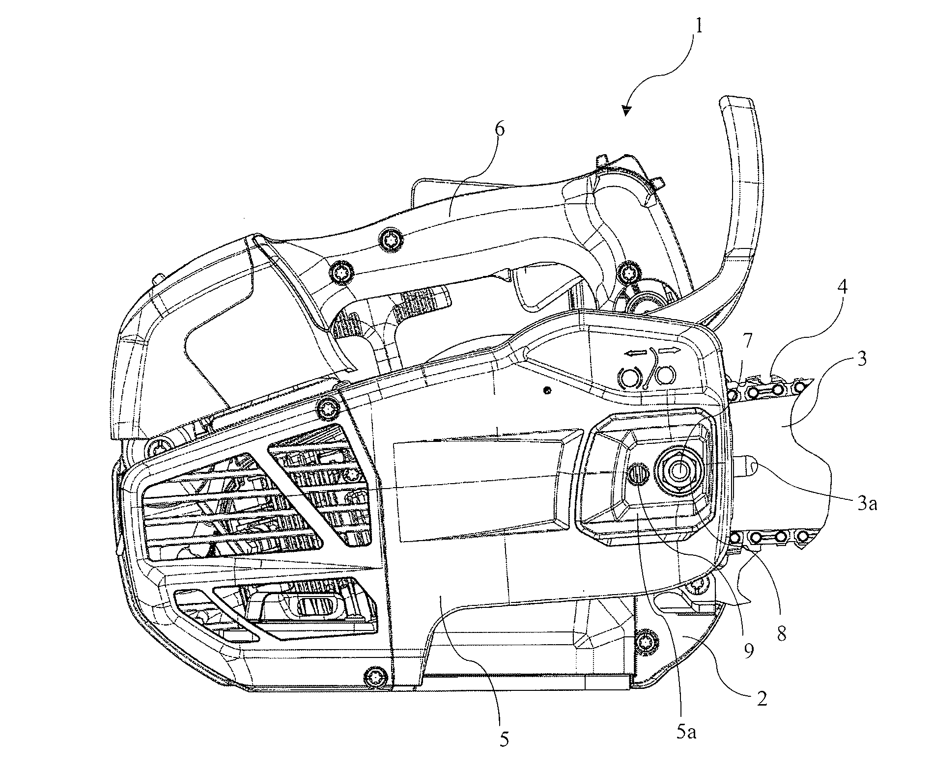
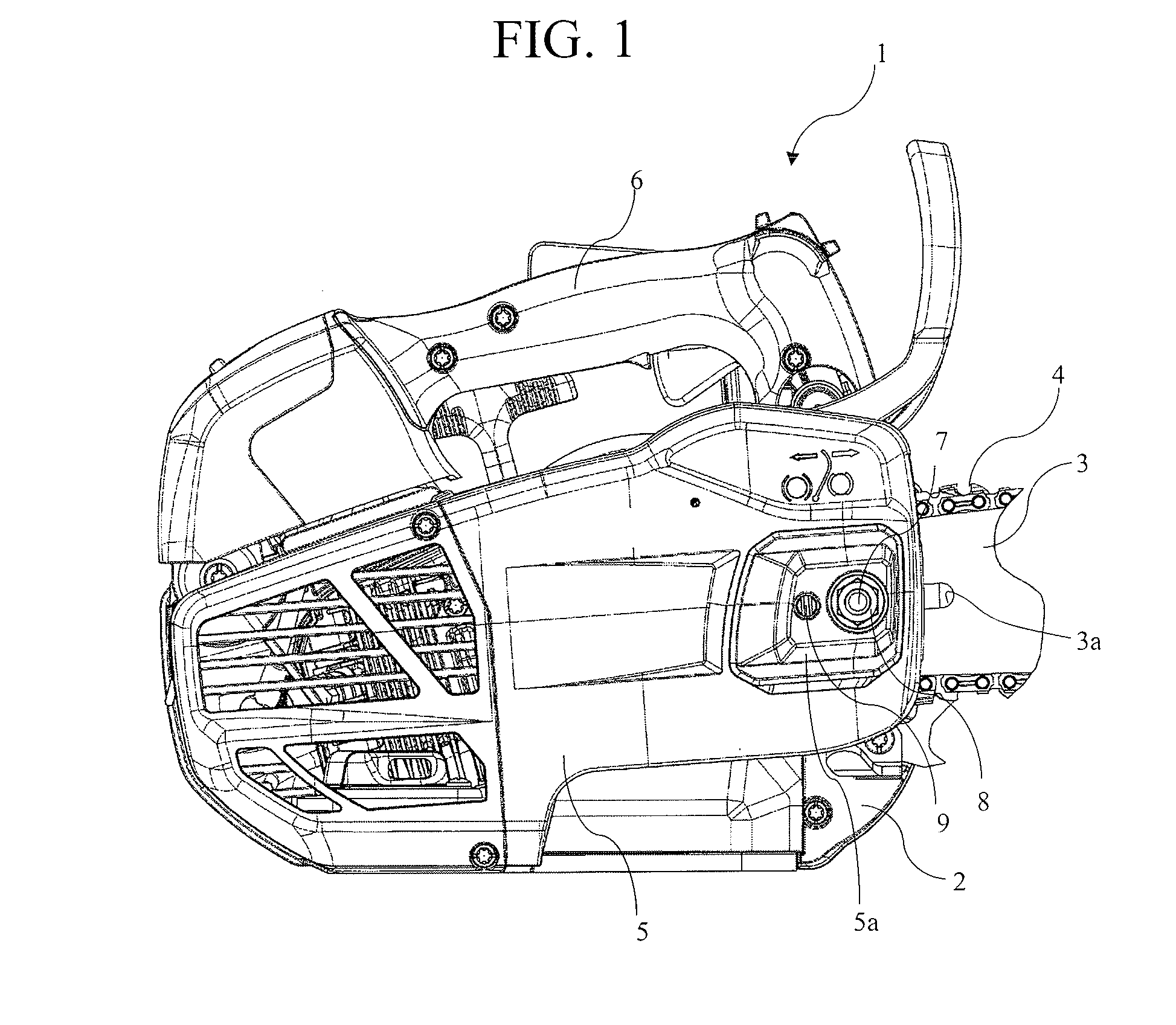
[0025]FIG. 1 illustrates the overall configuration of a chain saw according to an embodiment of the present invention.
[0026]In a chain saw 1, a guide bar 3 extending to the front side is mounted on a chain-saw main body 2. A saw chain 4 is wound around a peripheral edge portion of the guide bar 3.
[0027]In the chain-saw main body 2, the saw chain 4 is engaged with a sprocket (not illustrated) driven to be rotated by a motor, such as an engine or an electric motor, so that the saw chain 4 rotates around the peripheral edge portion of the guide bar 3.
[0028]An area in which a part of the guide bar 3, the sprocket, which is adjacent to the guide bar 3 and driven to be rotated with the saw chain 4 engaged therewith, and the like are disposed, is covered by a chain cover 5, and the chain cover 5 is mounted on the main body 2.
[0029]At the upper portion of the main body 2, a handle 6 in...
PUM
 Abstract
Description
Claims
Application Information